In one of our articles, we addressed different types of redundancy in NTP networks and high availability bonding was one of them. This setup implemented with Meinberg LANTIME systems assures the constant availability of an NTP server, even if the LAN port responsible for NTP traffic fails or the network infrastructure this port is connected to fails. We can achieve this by physical bonding of two LAN ports together and their proper settings over a web interface.
Let me show you how bonding can be configured on one of Meinberg LANTIME servers with V6 firmware. We log in to the LANTIME web interface and select Network settings-> Physical Network Configuration. For our example we choose LAN 0 and LAN 1 as bonding ports. First of all we have to connect them both with a patch cable over a switch, but even better is a connection through two independent switches to manage the case if one of them fails. Thus a single point of failure is moved lower down the network hierarchy (Figure 1).
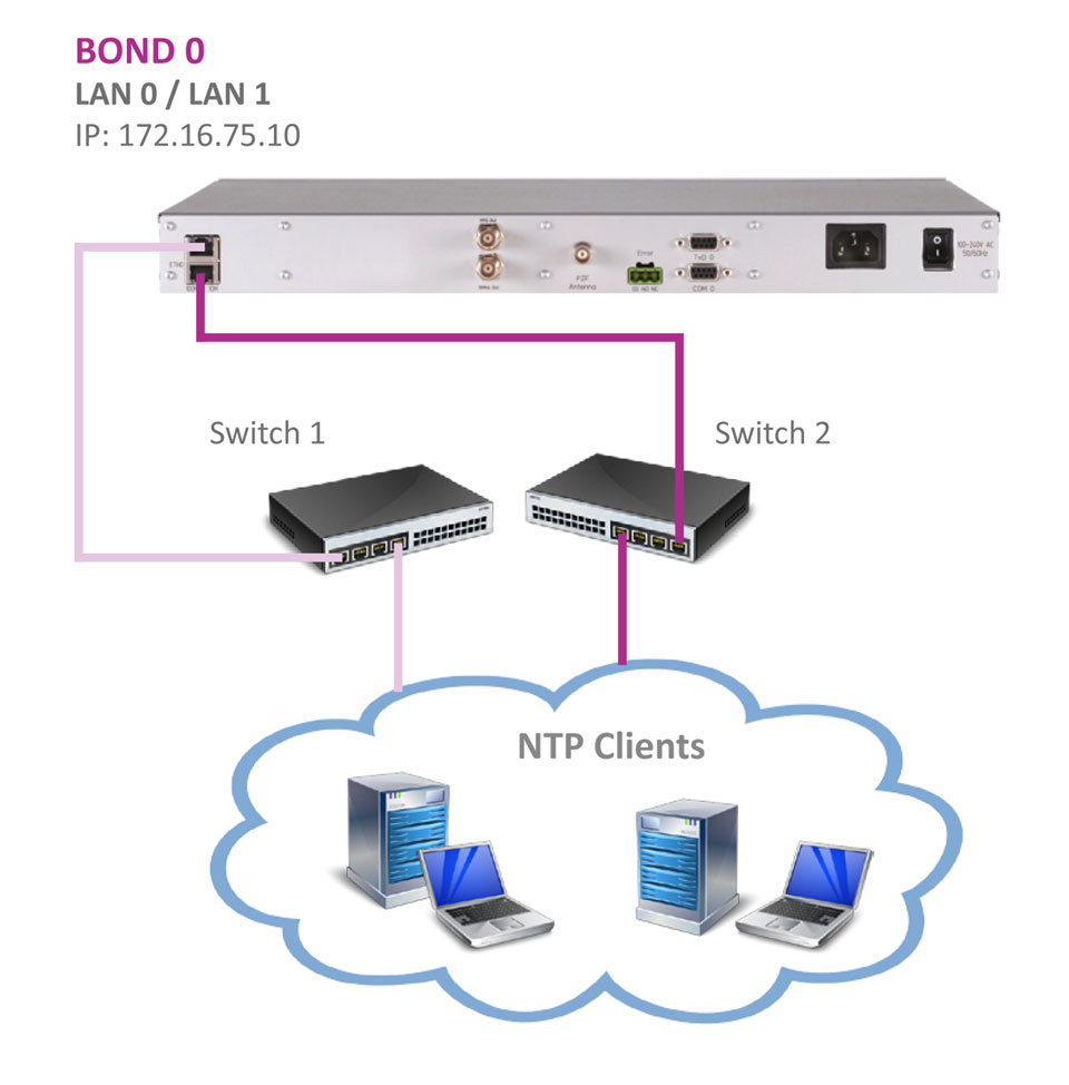 Figure 1: Bonding configuration setup with Meinberg LANTIME in an NTP network. The network is realized with two independent switches to provide redundancy if network infrastructure connected to either of the LAN port fails.
Next continue to the Physical Network Configuration tag -> Bonding section, where both selected ports should be assigned to the same bond, e.g. Bond 1 (see Figure 2). The rest of the LAN ports settings remain untouched.
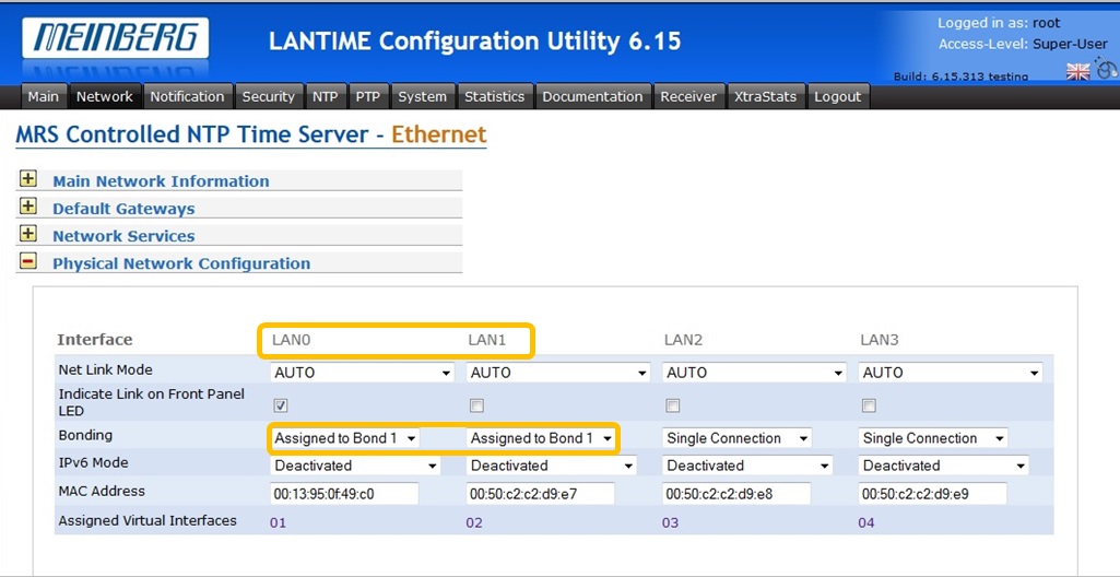
Figure 2: LAN 0 and LAN 1 are assigned to the same Bonding group.
In the web interface, continue to the Network Interfaces menu and then choose the Interface settings corresponding to LAN 0 and LAN 1, in our example Interface 01 and Interface 02 respectively.
Configure them as usual: IP address, netmask and additional virtual interfaces if required (Figure 3). Since both LAN ports are joined in a BOND now, they act as one port in the network. All virtual interfaces which have been assigned to either of Interface 01 or 02 are now available through the BOND interface as well.
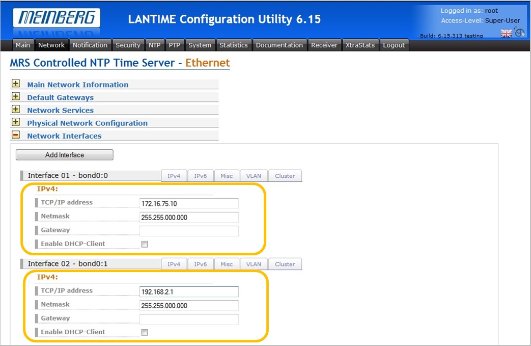
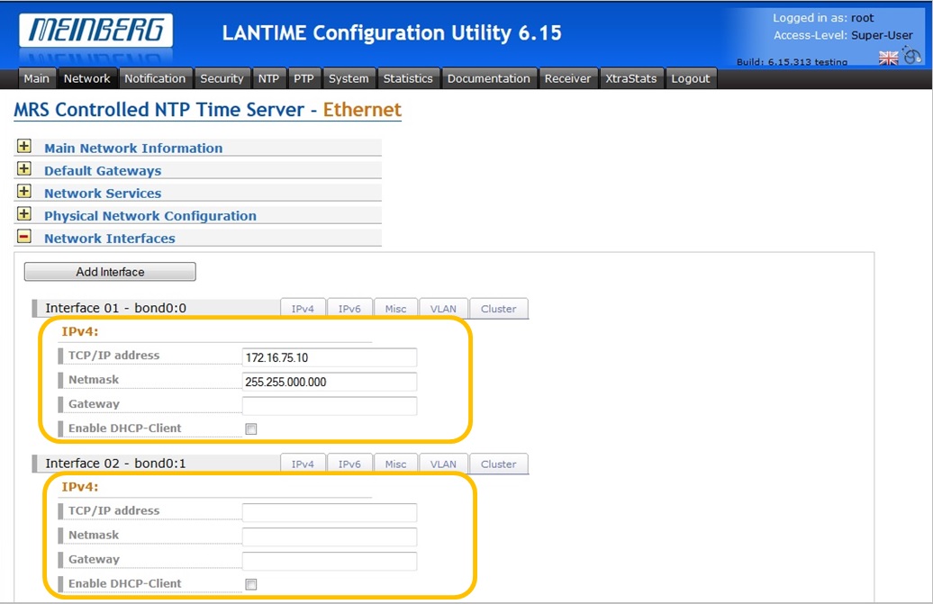
Figure 3: Configuration of LAN 0 and LAN 1 interfaces (left). If for instance LAN 1 is not used to synchronize clients in a separate subnet, then leave its network configuration empty as per the default (right), but still assign it to the bonding with LAN 0 as shown in Figure 2. The BOND interface inherits all settings from both underlying physical interfaces.
To check out if the bonding feature is working properly, try to ping the LAN 0 IP address from a command line program with a command:
ping 172.16.75.10 –t
-t is a parameter, used for an ongoing output. If you plug in and out the LAN 0 and LAN 1 patch cables alternately the ping output should continue without interruption as shown in Figure 4.
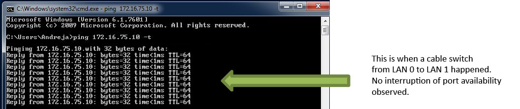
Figure 4: Uninterrupted ping output with a port switch between bonded LAN 0 and LAN 1.
Cluster and Bonding combined
If you are requiring redundancy in the event that one of NTP servers fails, and at the same time redundancy for high availability of network infrastructure, then consider combining Cluster and Bonding. Meinberg Cluster mode involves several servers which backup one another for case of a failure, whereas Bonding refers to each individual server and its high availability network connection. The Meinberg Cluster server setup has been discussed in the previous post, therefore we have enough knowledge to be able to configure both features now.
Let us go back to the web interface. Leave the bonding settings of your LANTIME untouched, proceed to the Network Interfaces menu and select a Cluster tag of the Interface 01 – bond0:0 (check Figure 5). Here a cluster IP shall be assigned to the bond0:0 interface. Please note that the cluster IP should be defined in the same subnet as the corresponding interface. In theory a cluster IP can be assigned to any of the bond interfaces originating from LAN 0 and LAN 1 virtual interfaces.
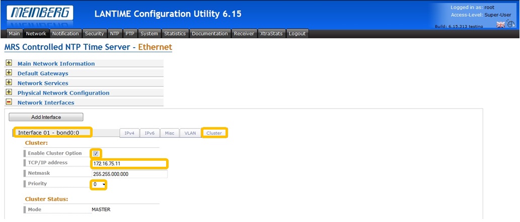
Figure 5: Cluster mode settings for Interface 01-bond0:0. The same cluster IP is assigned to the other servers in the cluster as well.
If you enjoyed this post, or have any questions left, feel free to leave a comment or question below.