Five Minute Facts About Packet Timing
By Andreja Jarc.
Synchronization in Power Networks
There are a few different timing technologies which are used for synchronization in power grids. Traditional power systems use IRIG-B which can deliver from 1 us to a few micro seconds accuracy, depending on whether you are using the TTL or AM version. The main drawbacks of IRIG-B is that it requires dedicated cabling for timing, and network delays are not automatically calibrated.
With the Network Time Protocol (NTP), due to fact that it is a two-way timing protocol, the network delays are calibrated automatically. In addition, NTP uses the data network which is more efficient in terms of cabling than IRIG-B. However, it can achieve only about 1ms typical accuracy.
On the other hand, PTP (Precision Time Protocol) delivers the best of IRIG-B and NTP: 100 ns to 1us of accuracy within a substation. Moreover, PTP does automatic network calibration and it uses the data network, therefore no extra cables are needed to transfer the time.
PTP in Substations
PTP Time in substations is distributed using power profiles. There are two profiles defined for power applications: IEC 61850-9-3 Utility Profile and the IEEE C37.238 Power Profile. Both profiles are almost identical with a few special settings in the Power Profile. They are designed for Layer-2 networks, either Ethernet, HSR or PRP. For details on HSR and PRP please refer to one of our previous posts. They use the Peer Delay measurement mechanism; therefore all switches need to have PTP support and are either transparent clocks or boundary clocks.
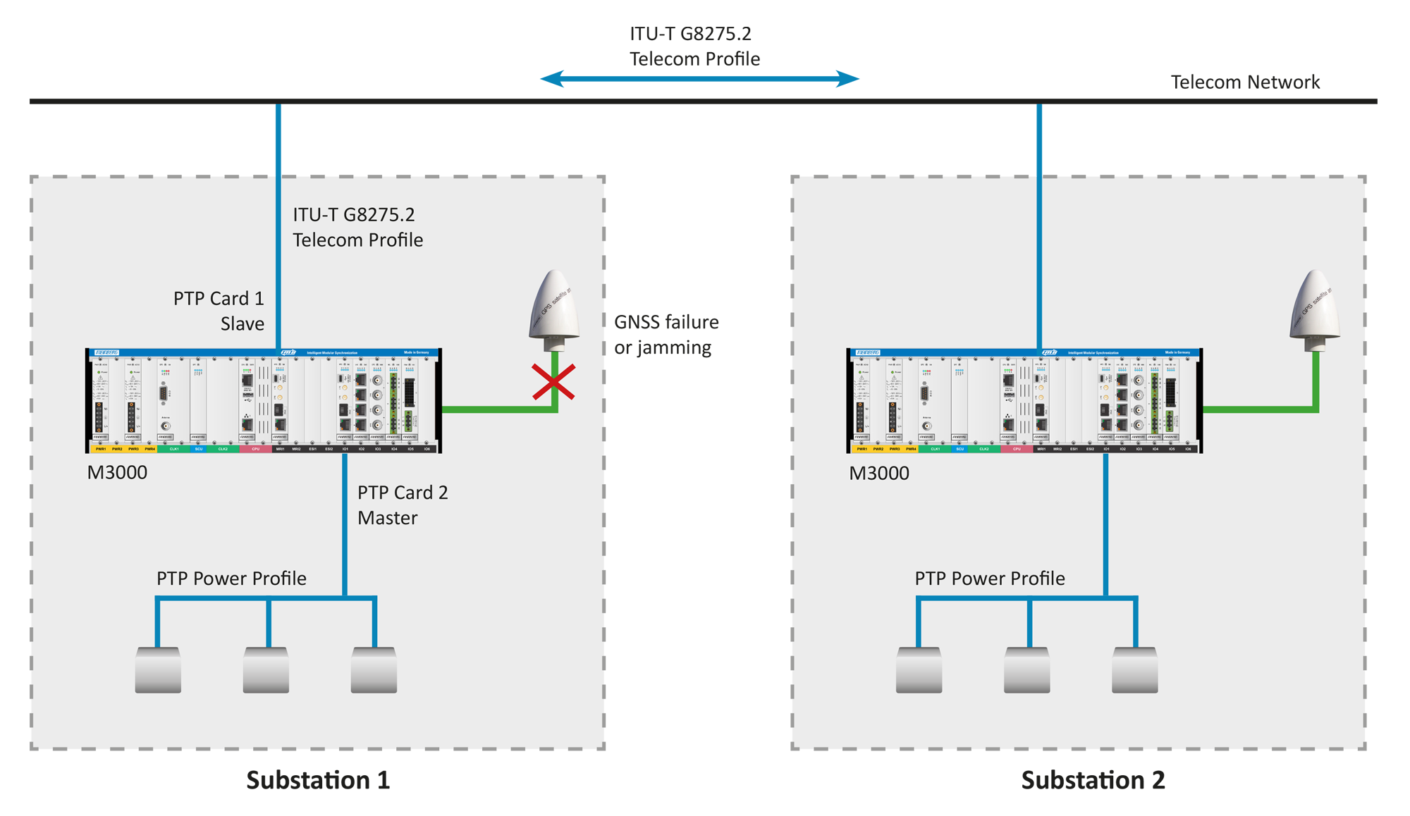
PTP can be used also to transfer timing from substation to substation. In this case the communication goes to an adjacent substation or to a SCADA network and the Substation gets timing from there. Such PTP inter-grid network can serve also as a failover in case of GPS failing or jamming.
Telecom Profile PTP for Inter-grid Network
For inter-grid network time transfer they would commonly use a Telecom Profile PTP (for example ITU-T G8275.2), because the inter-substation network is usually based on telecom technology. Basically, it is like a telecom network.
Some power grids are even using the Telecom Profile only, because within a substation they still have an IRIG-B network and will keep using that. In this case they need a device that can take PTP as an input signal from the external network and deliver IRIG out, and sometimes also NTP to a data network in a substation.
Configuration with a Meinberg System
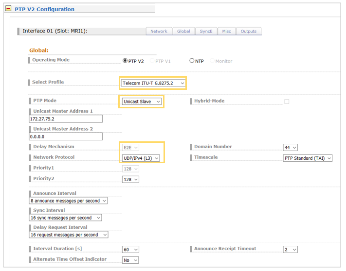
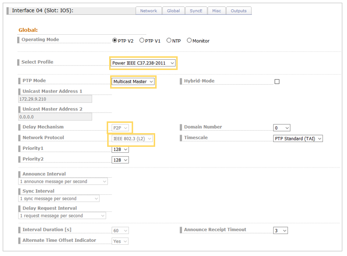
The Meinberg IMS (Intelligent Modular Synchronization) M3000 System can do such PTP translation between the Telecom and Power Profile. To do this, the system needs two separate PTP Cards. One PTP card is configured as a slave and is running the ITU-T G8275.2 Telecom Profile. The second card is configured as a master and is running the Power IEEE C37.238 or optionally the IEC 61850-9-3 Utility Profile. Depends which profile is used within a substation.
Let me show you how you can configure this setup in a LANTIME V6 Web GUI.
At this point, I would like to acknowledge my colleague Dr. Doug Arnold for his valuable technical contribution in the topic.
If you have a question about PTP or you need more information on configuration, send me an email to andreja.jarc[at]meinberg.de or visit our website at www.meinbergglobal.com.
Thanks for excellent article