In the latest release of our LANTIME firmware 6.24 you can find a new feature called Trusted Source. This additional functionality is much awaited by everyone who is looking for a method that will help to mitigate vulnerabilities of the GPS signal.
Anomalies in the GPS timing caused by unfriendly signal spoofing or transmission of incorrect data by the GPS system itself as observed on January 26th 2016 lead either to the loss of reception or even to incorrect time in a GPS synchronized timing receiver, if no additional measures are taken to mitigate the influence of these effects. Meinberg has implemented a so-called ‘trusted source’ method (TRS) – that allows connecting one or more additional time sources to a GPS receiver. The functionality of this kind of receiver with a Multi Reference Source (MRS) operation has been addressed in one of our previous posts.
The TRS Method is supported in Meinberg LANTIME Systems in combination with an external XHE Rubidium connected to the GPS receiver. The TRS enables deeper consistency checks of the received time.
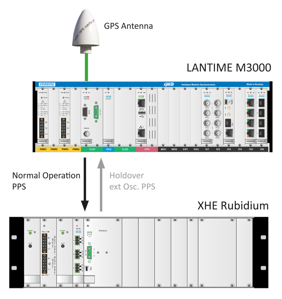 Figure 1: Trusted source setup including LANTIME M3000 with GPS180 receiver and an XHE Rubidium device. In normal operation, the external Rubidium is steered by PPS coming from the GPS clock. In holdover periods, on the other hand, the Rubidium becomes a master source and steers the reference clock with its PPS.
The external Rubidium acts as a holdover buffer that is synchronized by the MRS Master as long as the master is available. If the GPS Master fails or GPS for some reason starts delivering corrupted data the TRS will detect this as an offset limit violation. Consequently, the reference selection algorithm will discard the current master and the XHE rubidium source will become the new master for synchronization.
When the GPS signal reverts to normal operation and the time difference returns below the TRS limit, the GPS becomes the master source again.
Configuration of TRS in LANTIME Systems
Let me now explain the steps how to configure the TRS mode in your LANTIME.
First of all, the GPS source should be selected as source 1 in the priority list and the “ext. OSC” (referring to XHE Rubidium) should be configured as priority 2. All the rest of priority levels should be left unconfigured. You will find these settings in the LANTIME Web GUI-> Clock->GNS Clock->Source Priority.
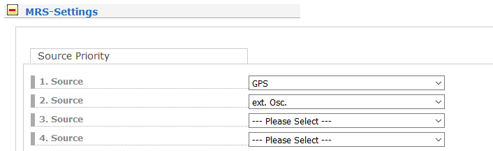 Figure 2: Priority list with GPS and ext. Osc. in MRS Settings.
Second, the IRSA Reference selection algorithm should be activated.
We configure a TRS limit the GPS Master source should comply with in the Precision field. In our example we configured 250ns which is the maximum allowed time deviation of the GPS receiver.
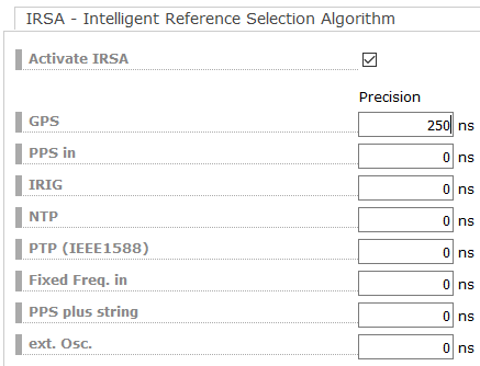 Figure 3: TRS offset limit for the GPS receiver.
Third, the TRS mode should be enabled by selecting “Use Trusted Source” for the GPS master. (LANTIME Web GUI-> Clock->GNS Clock->Features). The XHE Rubidium should be configured as “Is Trusted Source”.
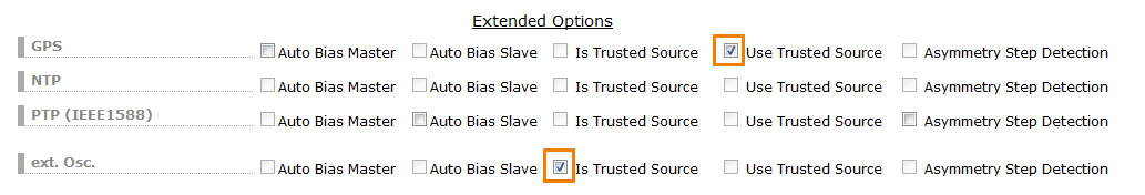 Figure 4: Activation of the TRS operation mode.
Finally, the GPS source should have enabled “Time of Day Source” and “Phase Source”, which means that the GPS is a source for both Time of Day and Phase. At the XHE Rubidium only the Phase Source should be enabled, since the atomic clock alone does not deliver a time of day information.
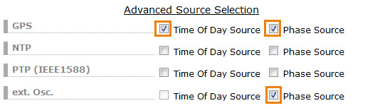
Figure 5: Time of Day and Phase information selection.
You can monitor the TRS operation in the MRS Status. As long as the time offset between GPS and XHE does not exceed the GPS precision value the normal operation status is shown as below.
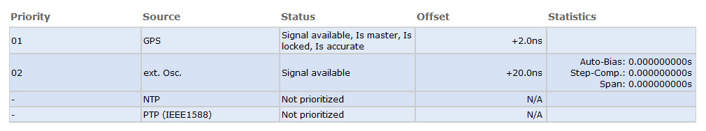 Figure 6: Status information in normal operation.
When the TRS limit is violated, the reference algorithm discards the current master and switches automatically to “ext. OSC” (i.e. XHE Rubidium) backup mode and the “TRS Limit violated” flag is shown in the status information of the GPS source.
The TRS Violation is listed also in the notification event matrix and can be activated for monitoring.
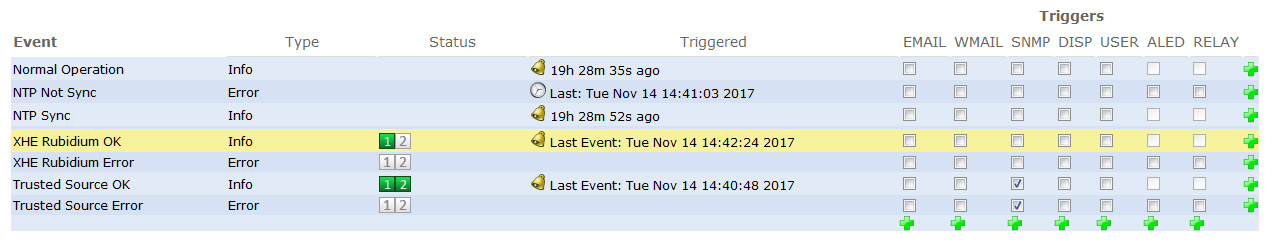 Figure 7: Selection of notification events for alarming and monitoring of the TRS operation.
Let me acknowledge at this point my colleague Andre Hartmann, the Managing Director of R&D at Meinberg for providing the technical expertise on the TRS feature.
I hope you find this post useful for your synchronization deployment. If you have any questions, write me to andreja.jarc[at]meinberg.de or visit our website at: www.meinbergglobal.com.
A GPS spoofing attack attempts to “deceive” a GPS receiver by broadcasting counterfeit GPS signals, structured to resemble a set of normal GPS signals, or by rebroadcasting genuine signals captured elsewhere or at a different time. These spoofed signals may be modified in such a way as to cause the receiver to estimate its position to be somewhere other than where it actually is, or to be located where it is but at a different time, as determined by the attacker.
Hello Shaun,
TRS acts basically at the ‘back-end’ of the receiver. It means that if the attacker tries to manipulate the receivers time
TRS does not use countermeasures within the receiver’s FW but simply recognizes that the GPS or GNSS receiver
provides a wrong time and deselects it as a time source. Of course there are some additional countermeasures
within the receivers FW to avoid or at least mitigate the effects of a spoofing attack, such as a position fix mode
that does not allow to move the receivers position after an initialization phase. However, these measures are implemented in the receiver’s firmware and
have nothing to do with the TRS algorithm that operates autonomously.