By Andreja Jarc.
Time can mean many things. For purpose of synchronization, we are trying to determine a sequence of events or we want to compare how long an event lasts.
Usually we are talking about the Time of Day (ToD), which represents a “wall clock time” – a specific time with hours, minutes, seconds and the corresponding date. We use the ToD for example for time stamping a PTP event packet when it is arriving or leaving a network port.
However, you cannot talk about the time without also talking about frequency. Frequency is a repeating occurrence of events. Its unit is Hertz, which tells you how many events occurred in a second. The reason why you can’t talk about time without frequency is, because every kind of clock e.g. a pendulum, mechanical clock or a crystal oscillator has a regular occurrence of events, which can be counted by a counter.
The next level of synchronization is phase synchronization. In this case we want that events happen at the same point of time. In phase synchronization we usually don’t care what the actual time is as long as events occur at the same moment.
There are many applications where the phase synchronization is needed and sufficient without having a ToD information. For example in measurement environments, where different parts of equipment are taking a measurement at the same time. Another example are Single Frequency Networks like DVB-T. Here the transmitters not only need to send out their information with the same frequency but also need to be phase aligned.
So, how can we apply this discussion about the ToD, phase and frequency to Meinberg Systems?
Let’s say you have a reference source from an atomic clock like Cesium, Rubidium or Hydrogen maser which can provide highly stable frequency and phase, but at the same time you may need the Time of Day as well. The ToD information cannot be delivered by the atomic clock alone.
In this case you can use a reference source combination, where one of the sources provides the ToD and the other source provides phase or frequency. Your oscillator will be steered first by a source with the ToD until it gets roughly adjusted and reaches the highest level of accuracy that can be achieved with that reference. After that the reference clock switches automatically to a more accurate source, for example an atomic clock that provides phase and frequency.
Configuration of your LANTIME System
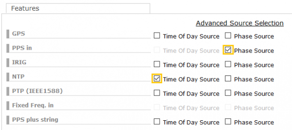
In the following example, we use NTP for the ToD synchronization and PPS for the phase. A configuration example in your LANTIME would look like this:
Figure 1: Configuration setup for the ToD, phase and frequency synchronization provided by different sources.
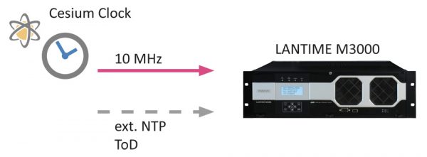
There are other use cases where a combination of input reference signal proves beneficial. One example for the radio broadcasting industry uses a combination of NTP and 10 MHz from a Cesium clock. In this case the reference clock steers roughly to the ToD coming from the NTP first. After setting the ToD, the source switches automatically to a highly accurate and stable 10 MHz frequency from an external atomic clock. For this case, a configuration in the LANTIME interface would look like this:
1. Source: 10 MHz for Frequency
2. Source: NTP for ToD
 Figure 2: A common synchronization setup in the broadcasting industry. Here, NTP is used for the ToD synchronization and highly stable 10 MHz signal coming from an atomic clock is used for frequency synchronization.
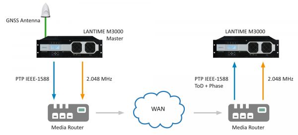
Another example would be the use of PTP IEEE1588 as an input signal coming from a WAN network, which may be exposed to a high jitter and therefore may have inferior quality. At the same time a highly accurate source for 2.048 MHz is available for frequency synchronization via the network infrastructure. In this case we use PTP to set the ToD and phase until the oscillator gets warmed up and locked. For the next level of accuracy the synchronization algorithm switches automatically to the 1. priority source which is a highly stable 2048 kHz frequency.
1. Source: 2.048 MHz Frequency only
2. Source: PTP over WAN for ToD and Phase
 Figure 3: Synchronization with PTP IEEE1588 for ToD and phase in combination with a highly stable 2.048MHz frequency signal.
If you have a question or a comment to this topic, please use the form below, write me an email to: andreja.jarc[at]meinberg.de or visit our website at: www.meinbergglobal.com.

Thanks, Andreja Jarc
For posting this article about ToD + Phase sync in timing networks. I would like to have confirmation from above sketch is that default EPOCH will be replaced to current ToD at media router.
If not, how 2.048Mhz clock is sent in packet network to slave node for recovering ToD? Pleas correct me if I am wrong.
Thanks,
Hari