Five Minute Facts About Packet Timing
By Doug Arnold.
The IEEE Standard for Synchrophaser Measurements for Power Systems (IEEE C37.118.1 -2011) recommends that phase measurement equipment in power systems by synchronized to UTC to within 1 μs. That is fairly strict timing requirement for a system that deals with voltages and currents at the low frequencies of only 50 or 60 Hz. So where does the 1 μs come from? Let me see if I can answer that in five minutes or less.
Power grid operators are responsible for a power grid which has becoming increasing complex. Once upon a time, power was generated by burning fossil fuels or nuclear reactors which generate power at constant rates in large power generation plants. Much of that power was consumed in incandescent lighting, which had the virtue of looking electrically like a simple resistor. Now more and more of the power is generated by solar panels and windmills, both of which have a strongly time dependent output, and can be large installations or individual homes or businesses. In addition more and more of the power is consumed in energy storage devices, which have a significant reactive components to their impedance. That’s right I’m talking about all the batteries we charge “now a days”. Batteries for cell phones, laptop computers, even cars!

Source: Electric powered car charging
To effectively monitor and control the increasingly complex power grids, grid operators are adding more synchrophaser measurement capability throughout the grid. These are time tagged measurements of voltage and current throughout the power grid. Operators can monitor the relationships between voltage and current due to reactive loads, compare the phase at two voltages which might be connected together to divert power from one part of the grid to another, or monitor the harmonic content of the signal. Often important data is aggregated from more than one phasor measurement unit, or PMU. The PMUs need to be synchronized so that the data can be directly compared in time. But how accurately? This brings us back to the IEEE C37.118.1 standard.

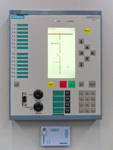
Synchrophaser measurement capability is often integrated with other power equipment such as a protective relay.
(Image reused from Wikimedia Commons)
Consider the measurement of a sinusoidal voltage, V = Vm cos(φ(t)). Hey, I never promised there wouldn’t be any math. Here φ(t) is the instantaneous phase which is 2πf0t+φo, with f0 the line frequency and φo the phase at t=0. As you, no doubt, recall this voltage can be represented as a phasor with real, Vr = Vm cos(φ(t)) and Vi= Vm sin(φ(t)) imaginary parts. If the timebase of the PMU is off by Δt, then a phase error of ε = 2πf0Δt will occur. The IEEE C37.118.1 standard defines a metric Total Vector Error (TVE) to quantify the damage to our measurement.
TVE2 = {[(Vr(meas)-Vr]2 + [(Vi(meas)-Vi]2}/{Vr2 + Vi2}
with
Vr(meas) = Vm cos(φ(t) +ε)
Vi(meas) = Vm sin(φ(t) +ε)
If you plug in the formulas for Vr, Vi, Vr(meas), and Vi(meas) then you can reduce it to
TVE2 = 2[1-cos(ε)]
It is highly recommend that you verify the math yourself if you are feeling nostalgic for the glory days when you learned trigonometry, or you are bored out of your mind.
In the case where the time base error is small compared to the line voltage period of 16.67 or 20 ms, then we can simplify even further. You do remember Taylor Series, don’t you?
TVE ≅ ε.
The IEEE standard recommends keeping the total vector error below 1%. That corresponds to time errors of ±26 μs for 60 Hz and ±31 μs for 50 Hz. If you stay below these time errors you keep the contribution to the TVE of the timing to within that goal of 1%. There are likely to be other errors in the measurement system as well. To make sure that timing does not use up much of the error budget the IEEE recommends timing accuracy of 1 μs, well below the thresholds we just calculated. That is realistic using IEEE 1588.
If you have any questions about PTP or NTP, don’t hesitate to send me an email at doug.arnold@meinberg-usa.com, or visit our website at www.meinbergglobal.com.

If you enjoyed this post, or have any questions left, feel free to leave a comment or question below.