Five Minute Facts about Packet Timing
Welcome to the next installment on my series of posts about timing equipment resilience in the language of the IEEE P1952 project. It’s time to talk about recovery … for clocks that is.
The first question about timing equipment recovering from an adversity is: Should it? Wait, what? I mean to say do you want the equipment to recover by itself or wait for you to clear the fault condition? The answer depends on your use case. Consider the case where some technical infrastructure needs timing to operate, and availability of that infrastructure is a critical performance requirement. An example of this might be radio heads in 5G telecom network. The radio heads must go offline if they determine that their time is likely out of spec. This it to ensure that they don’t start interfering with other radio heads and cell phones because they cannot be sure to transmit in their allotted time slots. Also, there are many 5G radio heads, so technical staff manually clearing faults is inefficient.
Another use case might involve making a precise measurement in an automated manufacturing test system. In this scenario it might be better to stop the measurement if there are any faults, rather than recording a measurement value whose accuracy is unknown. The inaccuracy might lead to false negatives or positives when it is time to pass or fail the product. It’s probably better if technical staff manually clear the fault condition and restart the measurement.
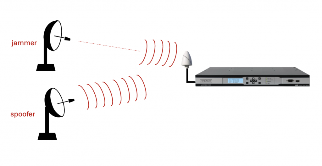
Here is a recovery challenge: Can the equipment not only detect an adversity, but also detect when it has gone away? Sometimes the latter is the hard part. One thing that might help is avoiding a complete reset when recovering from an adversity. Consider the case when the equipment goes into holdover due to GNSS jamming or detected spoofing. Before relocking to the GNSS signal the equipment can determine if the offset to GNSS is consistent with the expected drift of the local oscillator during the holdover interval. This can help mitigated against the dreaded jamming followed by spoofing attack depicted in Figure 1. And of course, the better the holdover oscillator the mode likely that the equipment could detect this attack.

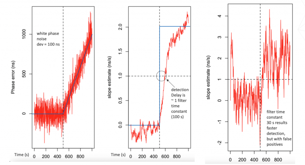
Since I’m on the subject, one last thing about holdover. If a clock enters holdover due to detecting a suspicious step or ramp in the input time from GNSS or PTP, the holdover setting for the local oscillator should be not the last value. The reason is that there is a delay in detecting suspicious inputs due to the necessity of filtering in your error detection statistic due to noise. Figure 2. Shows three graphs from simulated data. The leftmost graph shows the input signal with a ramp error. The middle graph shows a ramp detection statistic that detects the ramp, but with a delay due to the noise filtering time constant. The rightmost graph shows a faster detection with less filtering but also with false alarms. And you really can’t have false alarms. They will cause busy operations staff to speak in bad language, and learn to ignore alarms from the equipment.

If you have any questions about network timing, don’t hesitate to send me an email at doug.arnold@meinberg-usa.com, or visit our website at www.meinbergglobal.com.
If you enjoyed this post, or have any questions left, feel free to leave a comment or question below.