Five Ten Minute Facts about Packet Timing (sorry this one needs to be a little longer)
In my last post I talked about the behaviors that timing equipment should exhibit to achieve resilience in the face of adverse conditions, according to the draft standard IEEE P1952. One of these is the ability to detect an adversity that might impact the ability of the equipment to distribute precise timing. Some adversities are relatively easy. GNSS jamming or unintentional interference is pretty straight forward. The GNSS receiver is unlocked and reports a strong carrier, but no signal. Other adversities are trickier, such as GNSS spoofing, network asymmetry affecting PTP or cyber-attacks on PTP.
I posted previously about GNSS spoofing and how to detect it by comparing the GNSS receiver time to the time of your local clock. Keep in mind that two things about this approach is that there is a delay in detecting a spoofed signal if it presents itself gradually as a ramp error, especially since there will be noise in your measured difference between the two clocks that must be filtered out, and you want to avoid alarming on random noise. See this paper for an example discussion of these issues.
More and more GNSS receiver manufacturers are putting spoofing detection ability in the receiver itself. Such mechanism include:
• The received power level is too high. A GNSS spoofer has to send a signal at a higher power level to get the receiver to lock to the spoofed signal, instead of the real one.
• The GNSS solution is moving, but the receiver is configured in fixed position, timing mode.
It is also possible to get GNSS constellation information from a third party to verify that what your receiver is telling you is what the real GNSS constellation is broadcasting. For example the Fugro Atomicron system broadcasts integrity check values (ICVs) for GNSS satellite messages from geo-synchronous satellites that can be received using a standard GNSS antenna and a combo receiver. The receiver takes the key you get from the Atomicron server to check the ICV of the GNSS satellite messages.
An important adversity for PTP time transfer is network asymmetry. That is difference between the forward and reverse PTP message latencies. This difference shows up as error in the clock synchronization at the end devices. Such asymmetry tends to increase the more nodes there are between the timeTransmitter and the timeReceiver, especially if intervening devices do not include PTP support.
There are a number of ways to detect asymmetry. One is to field a device that receives PTP time in several different PTP domains, and then compares the received time. This is illustrated in Figure 1. The end device can compare the different received PTP domain times to each other and identify if one is substantially different from the others. This is what NTP does with its False Ticker Algorithm.

Another method is to place a PTP monitoring node, which has an independent source of time in a worst-case position in the network to determine if the accumulated asymmetry at that position in the network exceeds acceptable limits. This is illustrated in Figure 2.
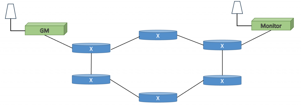
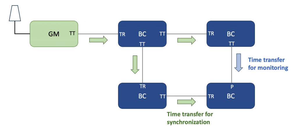
Asymmetry can also be detected in PTP networks where Boundary Clocks form a mesh network. The Best TimeTransmitter Clock Algorithm will set some of the BC ports to the passive state to break timing loops. The use of this technique has been described by the International Telecommunications Union in the technical recommendation that defines one a PTP Profile for full on path support, ITU-T G.8275.1. An illustration is shown in Figure 3.
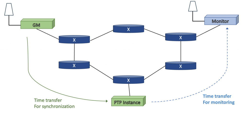
Lastly Asymmetry can be detected by measurement through the network via reverse PTP. This mechanism is not yet part of IEEE 1588, but proprietary implementations exist. The basic concept is illustrated in Figure 4. A timeReceivers estimate of the PTP domain time is transferred to a monitoring node that has accurate time, via GNSS or a direct connection to the GM. Ideally the monitoring node should be topologically far from the GM such that the network paths from the Gm to the timeReceiver and from the timeReceiver to the monitoring node are different. Note that since PTP is used to measure PTP, the measurement error is approximately as large as the thing it is measuring so this is a somewhat crude estimate. Also the clock difference detected at the monitor indicates a problem in either the GM->TR path or the TR->monitor path. Further investigation is needed to determine which it is.
PTP cyber-attacks can involve message manipulation, message injection, or message delays. Message manipulation can be detected using the ATHENTICATION TLV, or standard network security mechanism such as IPSec or MACsec, all of which includes an ICV for the message. Message injection can be detected when the security mechanism includes a key server that checks to see if a device is authorized to get keys. Some people are looking into the concept of only protecting the Announce message, and using a lucky packet filter to determine which Sync or Delay_Request messages are false. The general concept of the lucky packet filter is illustrated in Figure 5.

Delay attacks are the hardest to detect because it can’t be detected with cryptography, since no messages are altered or injected, they are only held up in one direction. However, since this is an artificially created form of asymmetry, then all of the techniques for detecting asymmetry will work.
If you have any questions about network timing, don’t hesitate to send me an email at doug.arnold@meinberg-usa.com, or visit our website at www.meinbergglobal.com.
If you enjoyed this post, or have any questions left, feel free to leave a comment or question below.