5 Minute Facts About Packet Timing
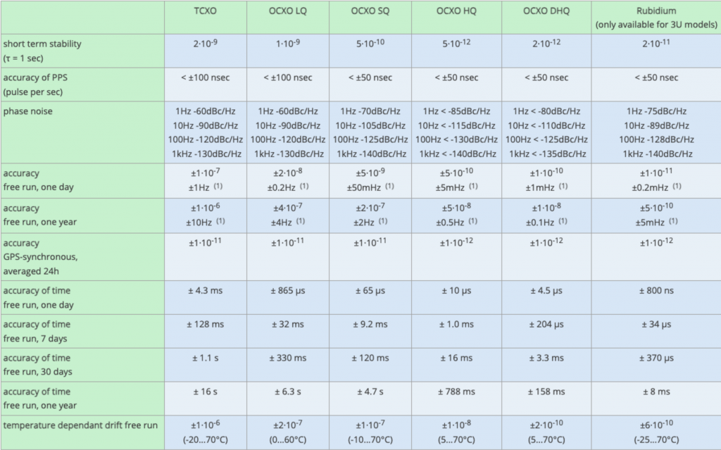
You have a holdover requirement, and you need to select an oscillator from the choices presented to you by your timing equipment vendor. More stable oscillators are better, but they also cost more. You want to know which is the least expensive option that meets your requirement. However, the vendor data sheets describing the oscillator choices aren’t necessarily stating the oscillator performance in the way that you need. For example, let’s say that you need a GNSS steered time server to stay within 5 𝝁s for at least 4 hours after the time server loses GNSS. And further let’s say that the vendor’s data sheet has a table like the one below. This is the actual current worst case performance specifications for Meinberg timeserver oscillator options. So, what do you do with all these numbers? You use the oscillator equation, and the following guidance.

First, if worst case is what you care about, make sure that the vendor is giving you those values, not typical, not 1 sigma. You need at least 3 sigma values. I give you permission to badger the vendor for the information you need. Ask questions. Next consider your requirement. You want to know what happens over 4 hours, but the table doesn’t show that. Use the time interval that is of a similar order of magnitude. Short term stability of the oscillator isn’t relevant to this requirement because those effects tend to average out after a minute or so. Similarly, what happens after a week, a month or year, is too long to matter for this requirement. So, you can ignore all of that. Use the 24-hour data, it is the closest to the time interval you care about. Second, if you have a temperature-controlled environment you can ignore the temperature dependent drift.
Now let’s get to the oscillator equation:
x(t) = x0 + y0*t +D*t2/2 + E(t)
Here x(t) is the phase error (time error) starting from the beginning of holdover, x0 is x(t=0), y0 is the fractional frequency error at t=0, D is the fractional frequency drift (rate of change per unit time), and E represents errors due to environmental effects. Usually, the dominant environmental effect is temperature variation. In our example we are going to ignore E. Wait, what is with the x’s and y’s? Why not something like 𝛥t and 𝛥f? Well x and y are traditionally used in the timing industry. Consider this a barrier to entry in the precise timing business that you have just overcome.
We are looking for x(th) < 5 𝝁s if th is the required holdover time. For x0 we use the Accuracy of PPS number, for y0 the GPS synchronized accuracy (24 hour average), and for D the Accuracy free run one day/(1 day). Let’s use units of seconds for time, time interval and time error. Therefore we need the drift to be in units of fractional frequency error per second, that is 1 day = 86400 seconds, and the holdover time is 14400 seconds.
Plugging in the numbers for the oscillators listed gives:
| Oscillator type Initial time error (s) | Initial time error (s) | Initial frequency error | Frequency drift/second | Error after 4 hours |
| TCXO | 1E-7 | 1E-11 | 1.16E-12 | 1.21E-04 |
| OCXO LQ | 1E-7 | 1E-11 | 2.31E-13 | 2.42E-05 |
| OCXO SQ | 5E-8 | 1E-11 | 5.79E-14 | 6.20E-06 |
| OCXO HQ | 5E-8 | 1E-12 | 5.79E-15 | 6.65E-07 |
| OCXO DHQ | 5E-8 | 1E-12 | 1.16E-15 | 1.85E-07 |
| Rb | 5E-8 | 1E-12 | 1.16E-16 | 7.64E-08 |
We need a holdover error below 5 𝝁s or 5E-6 seconds. From the table we can see that the OCXO SQ doesn’t quite cut it for this use case, but the OCXO HQ does.
What if we were outdoors, or some other environment that is not temperature controlled. For worst case analysis assume that immediately after going into holdover you also get a large temperature change. Therefore, replace the initial frequency error with the temperature dependent drift, free run. You did say worst case, right? Now the table looks like this:
| Oscillator type Initial time error (s) | Initial time error (s) | Initial frequency error | Frequency drift/second | Error after 4 hours |
| TCXO | 1E-7 | 1E-6 | 1.16E-12 | 1.45E-02 |
| OCXO LQ | 1E-7 | 2E-7 | 2.31E-13 | 2.90E-03 |
| OCXO SQ | 5E-8 | 1E-7 | 5.79E-14 | 1.45E-03 |
| OCXO HQ | 5E-8 | 1E-8 | 5.79E-15 | 1.45E-04 |
| OCXO DHQ | 5E-8 | 2E-10 | 1.16E-15 | 3.05E-06 |
| Rb | 5E-8 | 6E-10 | 1.16E-16 | 8.70E-06 |
In this case you will need a double oven (DHQ) OCXO. Even the Rb doesn’t qualify. Sometimes when temperature effects are dominant a high end OCXO is better than an atomic clock.
If you have any questions feel free to send me email at doug.arnold@meinberg-usa.com or check out the rest of the Meinberg website at https://www.meinbergglobal.com
Hi,
We have a LANTIME 1000 with two PTP interfaces. One MRI1 and one ESI1. The MRI1 is currently working as multicast master. Normally it is using a GPS receiver as reference and the Clock Class value is 6. If the receiver is defect the system will switch to Clock Class 7 and, in our case use the internal oscillator as reference. But, here is my question, for how long will it stay in clock class 7? The internal oscillator will drift so I assume that after some time it will switch to another Clock Class value?
Regards,
Per Magnusson
The length of time it will stay in Clock CLass 7 depends on the oscillator stability and the value of the maximum additional clock error due to oscillator drift that you can configure in one of the management interfaces, e.g. web.