Five-minute facts about packet timing
This is part 2 of a two-part description of the Best Master Clock Algorithm (BMCA). In Part 1 we listed the information that is considered in the BMCA and what the priorities are amongst those quantities. You can think of this information as the clock credentials. If you missed part 1, then you should read that first. In Part 2 we will talk about how that information is used to by PTP nodes to choose the states that their ports should be in.
Figure 1 shows that states of a Master-only Ordinary Clock (OC). Recall that an OC is a one-port PTP node, intended act as either a Grandmaster (GM) or a slave clock. A Master-only OC is typically a time server with a GNSS receiver that is intended to serve either as the active GM of the PTP domain, or as a backup GM. When it is ready to be a backup it will be in the Passive state. Note that the backup GM knows to be in the Passive state because it received an announce message from a clock with better clock credentials (see part 1 of this discussion for what counts as better). The Pre-master is a transition state intended to make sure that no Announce messages are arriving from better clocks. The Pre-master state creates a short delay before an OC becomes the GM. This delay is intended to reduce the number of port state transitions in the network when Announce messages are dropped in the network or there is a change in GM in the PTP domain.
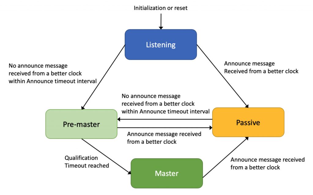
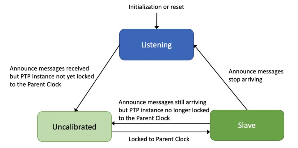
Figure 2 shows the same state diagram for a Slave-only OC. Just as the case with the Master-only OC, the slave only OC will remain in the listening state until it receives an Announce message from a better clock, then it will be in the uncalibrated state until it has been able to set or steer its PTP clock to the time of the GM to within its accuracy specification. After that it will be in the Slave state.
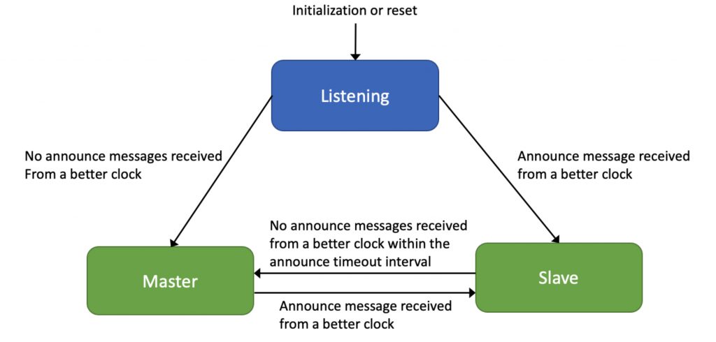
In some applications it is desirable to always have some PTP node acting as the GM, even if it is a device intended to be a Slave in normal operation. This might be a holdover situation for the PTP domain when the active GM becomes unavailable. Figure 3 shows a simplified view of an OC that can act as either a GM or Slave. For simplicity the transitional states Pre-master, and uncalibrated have been omitted. Not all PTP Profiles include these transitional states. For example, IEEE 802.1AS does not include them.
The BMCA operation in a Boundary Clock (BC) is more complicated than it is in an OC, because the state of a port depends on not just what Announce message the port receives, but also on what is received on the other ports as well. Normally a BC will set one port in the Slave state and the other ports in the Master states. The port in the Slave state will receive time from the GM, or an upstream BC, and that time will be used to set the BCs PTP clock. The BC’s PTP clock will then provide time for PTP messages transmitted on the remaining ports, which are in the Master state.
In Figure 4 Port 1 is not selected as the Slave port because it does not receive any Announce messages, in other words it is not connected to a PTP port in the Master state. Port 2 does receive Announce messages, but not from a clock as good that received on Ports 3 and 4. Port 3 is selected to be the port set to the Slave state over Port 4 because it received Announce messages from the same GM but through fewer intervening BCs, as indicated by the received steps removed value.
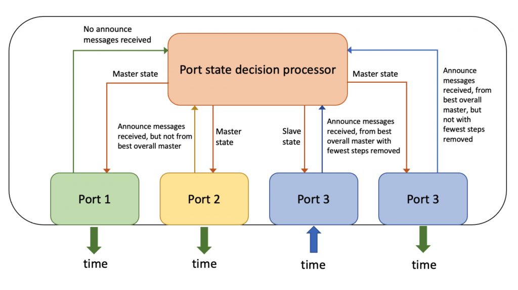
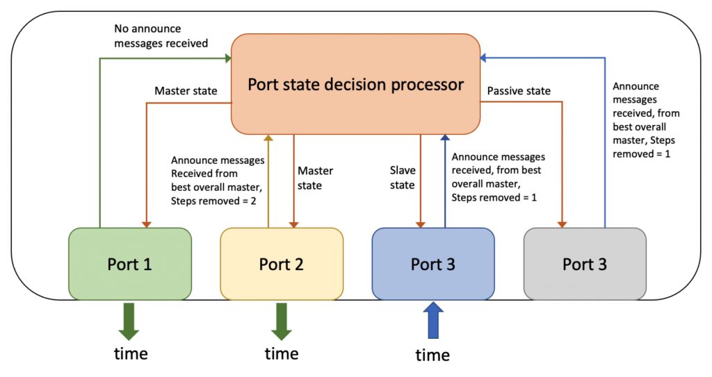
The situation depicted in Figure 5 is the same as that in Figure 4 except that Ports 4 and 5 receive Announce messages from the same GM each with the same number of steps removed. In this case the lower Port number, Port 3, is selected as the port in the Slave state, and Port 4 is put in the Passive state. In BC ports are put in the Passive state for the purpose of breaking timing loops, in the case that timing loops are not otherwise prevented by a transport layer protocol like the Rapid Spanning Tree Protocol.
If you have any questions about packet timing, don’t hesitate to send me an email at doug.arnold@meinberg-usa.com, or visit our website at www.meinbergglobal.com.
First time I hear about the removed steps value being used in BC for slave port election. Very useful, thank you very much !
You are so welcome.
Thank you for the informative blog!
Question on Figure 5. If Port 3 & Port 4 both receives the same PTP GM announce and steps removed messages advertised by two different BCs with different accuracies. What determines that Port 3 becomes Slave state and Port 4 Passive state? Would BCs’ timing properties(accuracy, offset from Master etc) matter?
If Port 3 went down, Port 4 will transition to the Slave state. But when Port 3 came back up, would Port 4’s role flipped back to Passive?
Also, Figure 4&5 is missing Port 4 labels.