Five-minute facts about packet timing
I previously posted about the Best Master Clock Algorithm or BMCA. Nevertheless, this aspect of the Precision Time Protocol (PTP) continues to stimulate questions from equipment designers and network operators. So, I will attempt to describe it in more detail, which will be spread over two posts. In this post I will briefly explain the purpose of the BMCA and how it works, and in some detail how potential master clocks are ranked in order to determine which is the Best Master Clock.
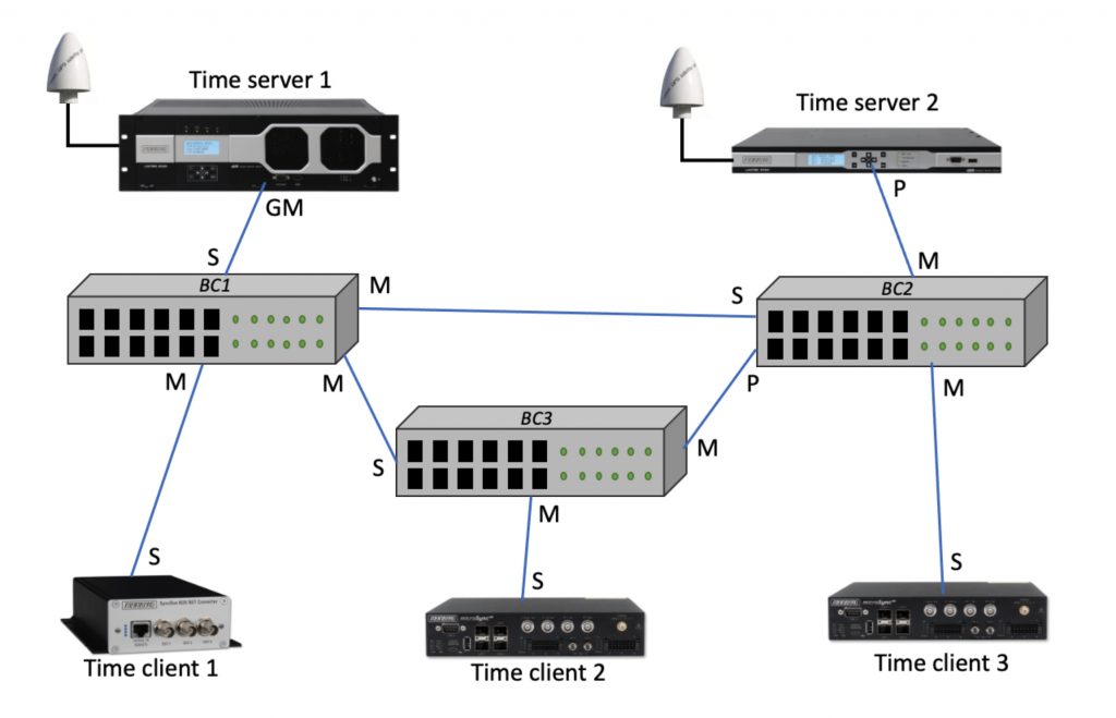
First, the purpose of the BMCA is to create a timing spanning tree, or timing hierarchy, for the orderly distribution of timing distribution. This might not be the same as the Ethernet spanning tree for message connectivity. An example PTP timing spanning tree is shown in Figure 1. An important property of PTP is this spanning tree can occur automatically without a network operator manually configuring it. One might form a timing spanning tree by having all the PTP nodes exchange timing capabilities with each other and then having the nodes run the same algorithm to determine the states of the PTP ports. Or, all of the PTP nodes might send their properties to a central server which runs the algorithm and tells each node what to do. The BMCA doesn’t use either of these approaches. Instead, the complete hierarchy is formed entirely by individual PTP nodes deciding which state each port should be in by looking at Announce messages that the node receives from other PTP ports that are in the master state. So PTP nodes don’t know, or need to know, what is going on at other PTP nodes unless they are communicating with them. This property makes the BMCA simpler than either of the other possible schemes I mentioned, and yet it still works.
Just to be clear, in this post and the companion post I am talking about the default BMCA defined in IEEE 1588, not one of the variations which some of the PTP profiles define. Also, I am strictly talking about multicast or mixed multicast/unicast PTP, not unicast PTP. One last qualifier: the BMCA runs independently in each PTP domain, and PTP domains do not interact with respect to the BMCA. PTP instances operating in one domain ignore messages in any other domain, as differentiated by domain number.
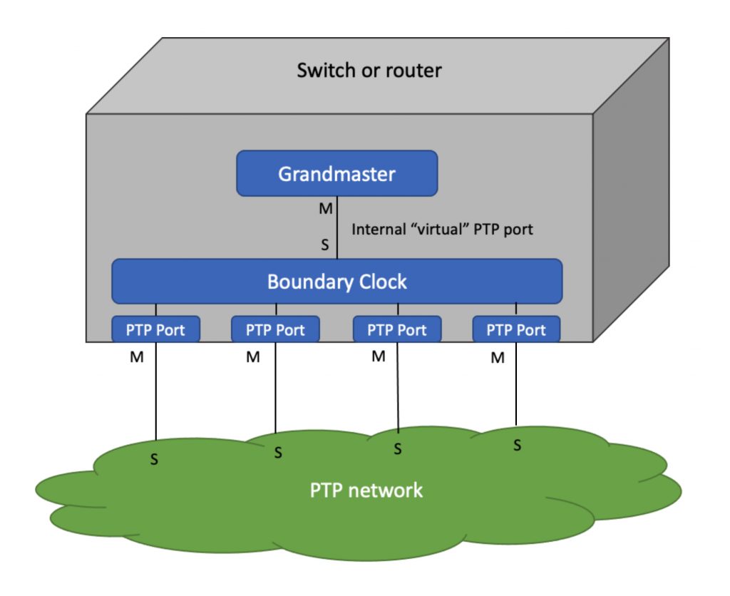
Referring again to Figure 1, all one port PTP nodes, called Ordinary Clocks (OCs) are acting as either the Grandmaster (GM), a Passive (backup to the GM), or a consumer of time acting in the Slave state. They are connected either by Boundary Clocks (BC) or Transparent Clocks (TC). TCs do not participate in the BMCA so they are not discussed here. BCs do, so I will address those in some detail in part 2. Note also that it is allowed that a BC can become the GM. Perhaps the BC has a good oscillator for holdover when the primary time server acting as GM is unavailable, or perhaps the BC has a GNSS receiver. One way to think of a BC acting as the GM is to think of it as an OC and a BC in the same box with an internal (virtual) connection. This model of a BC in the GM state is illustrated in Figure 2. Note that in the BMCA the term GM refers to a state that a PTP port might be in some of time, not a device. Companies that sell time servers capable of acting as the GM of a PTP network will often call the device a GM, but in the language of IEEE 1588 GM is not a device type like OC, BC or TC.
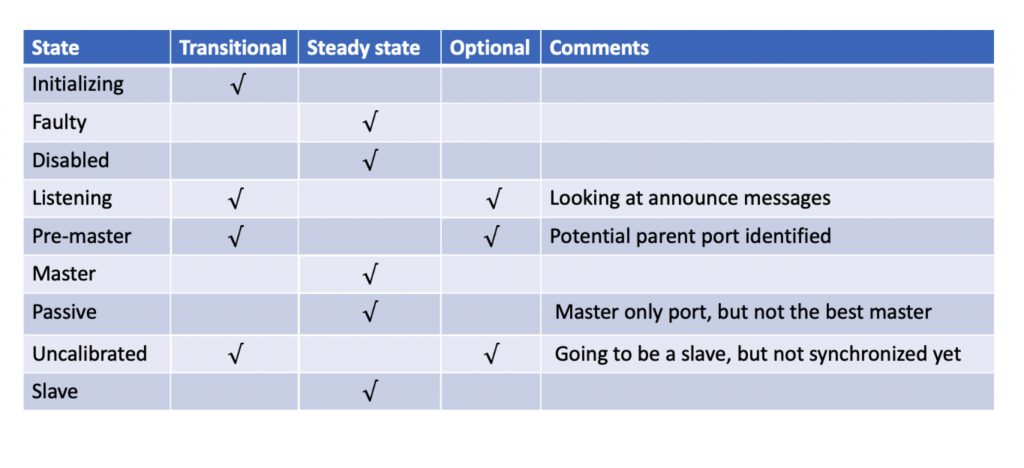
Speaking of state, the states that PTP port can be in are shown in Table 1. Some of the transitional states are optional and not used in all PTP profiles. The purpose of the BMCA is to place PTP ports in Master, Slave or Passive states.
Any PTP port in the Master state periodically sends Announce messages to the general PTP multicast address. The fields in this message contain the attributes used by the BMCA, shown in Table 2. When comparing two clocks you compare the attributes in the Announce message, or in the Announce message a PTP port would send if it were in the master state. The attributes are compared in the order that they are listed in Table 2, from top to bottom. And when they are compared, the lowest number wins. This is illustrated graphically in Figure 3. A critical point is that once a difference is found in values of the same attributes between clocks then the remaining attributes are ignored.
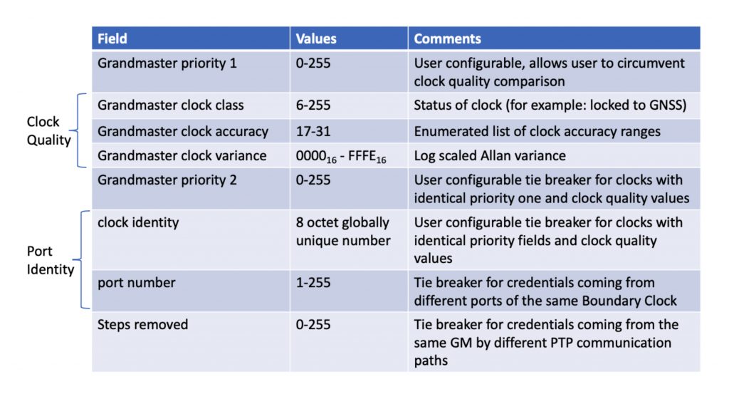
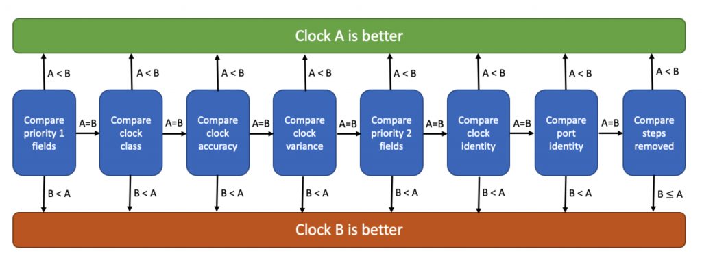
The priority 1 attribute is configurable by the network operator, basically for purpose of circumventing the BMCA and setting your own clock priority. Don’t do this. It could mean for example that a time server that has lost its GNSS signal will be considered better than one that hasn’t. I recommend always setting this attribute to the same value in every PTP node. Many PTP profiles require that priority 1 attribute is set to one specific value in all PTP nodes.
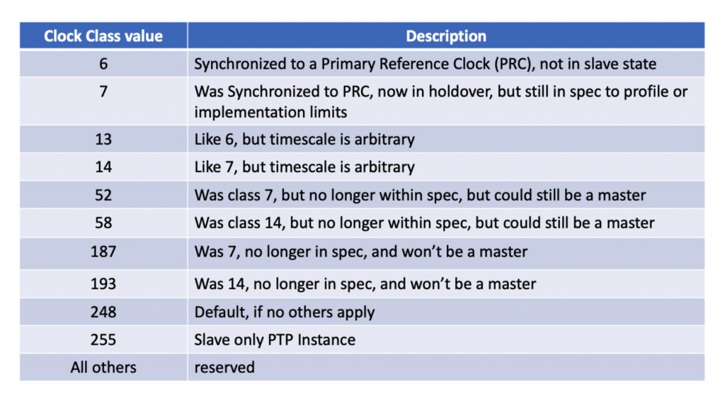
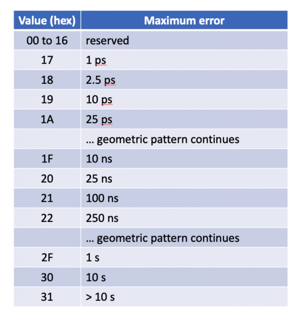
Table 3 shows the Clock Class values. You can think of these as the clock status. Table 4 shows the geometric pattern of the enumerate Clock Accuracy ranges. Clock Variance is, well … complicated. You take the Time Variance, based on the Allan Variance of the timestamping clock, take the log based 2 of that, multiply by 256, apply hysteresis if you are computing it dynamically, represent it as a two’s compliment hexadecimal, and add 0x8000 ignoring any overflow. If you did all that correctly you get a number (also I’m impressed). Smaller means less variance, and therefore a better clock.
I fear that I have already exceeded five minutes so I will stop here for now. In the BMCS Deep Dive Part 2 I will outline how a PTP node decides which states to set its port or ports in.
If you have any questions about packet timing, don’t hesitate to send me an email at doug.arnold@meinberg-usa.com, or visit our website at www.meinbergglobal.com.
If you enjoyed this post, or have any questions left, feel free to leave a comment or question below.