5 minute facts about packet timing
In a previous post I talked about the new redundant networking protocols High Availability Seamless Redundancy (HSR) and Parallel Redundancy Protocol (PRP). These protocols are defined in the IEC 62439-3 standard. Today I want to talk in more detail about PRP devices and networks.
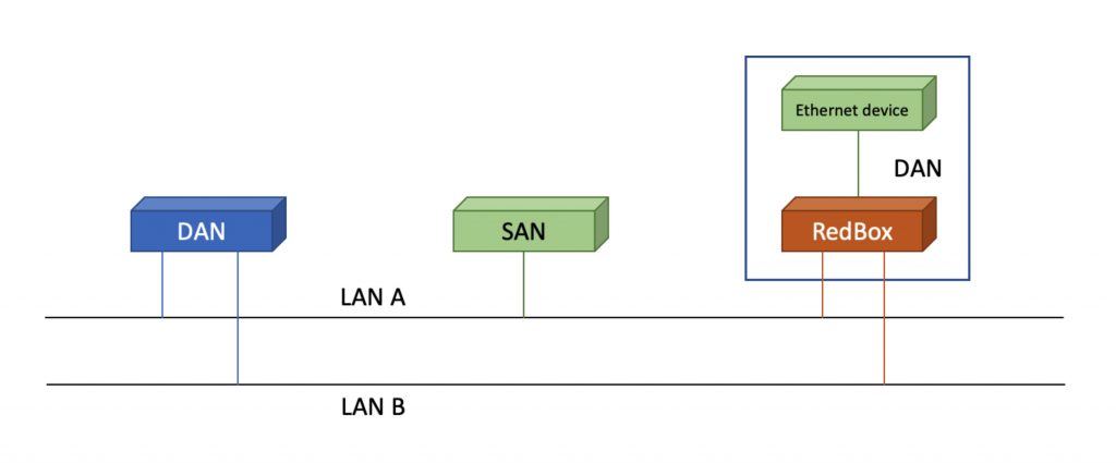
Recall that a PRP network has two parallel Ethernet LANS that devices can connect to. Figure 1. Shows the different ways a device can attach to PRP LANs. Doubly attached nodes (DANs) connect to both LANs. Singling attached nodes (SANs) connect to only one of the LANs. The SAN option allows one port devices to connect to the PRP network. A SAN does not need to have redundant hardware, but it gives up the benefits of higher availability via redundancy. An ordinary Ethernet device can connect to a PRP network AND get the benefits or redundancy by connecting to a redundancy box (RedBox). The Redbox translates between plain Ethernet and PRP.
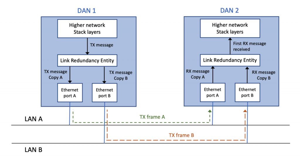
The way this works is shown in Figure 2. On transmission, a DAN or a RedBox receive a message to translate from the higher layers of the network stack and make two copies of the message, identical except for the LanID in the PRP header, and in the resulting checksum. The two copies of the message are transmitted into the two PRP LANs. On reception the DAN or RedBox sends the first copy of the message to the higher network stack layers and discards the second copy of the message.
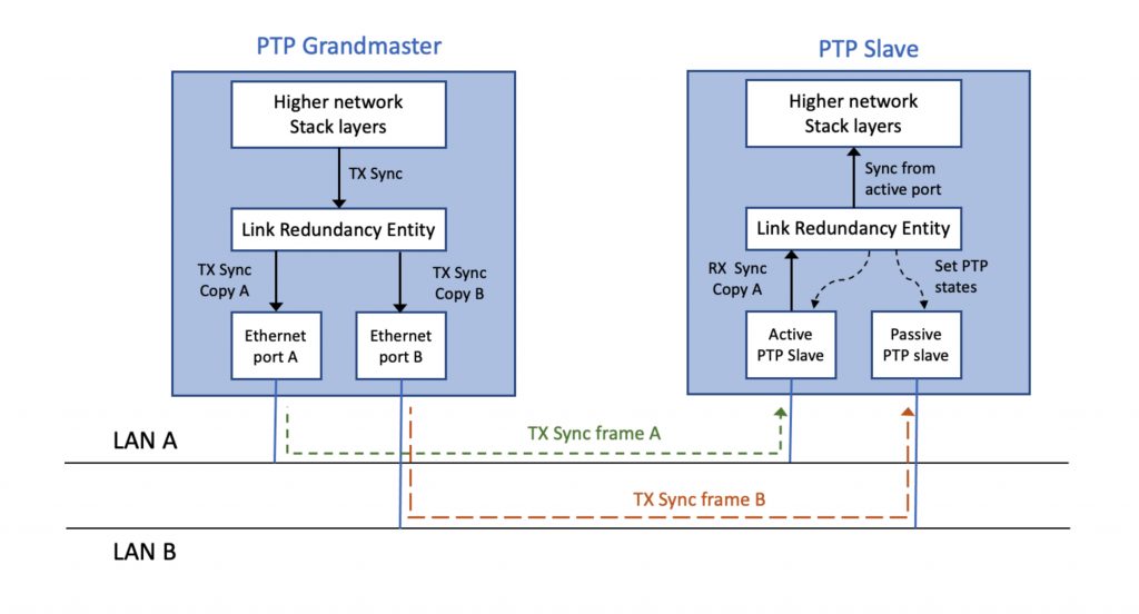
IEC 62439-3 also defines a mapping for PTP over PRP, depicted in Figure 3. Note how PTP traffic is treated differently than other PRP traffic. At the PTP slave, instead of forwarding the first received copy of a PTP message, to the PTP applications, one port is selected to be active, and the other one passive. The reason is that timing jitter could be increased by, for example, accepting the Sync message sometimes from port A and sometimes from Port B instead of consistently from the same port. The PTP slave still benefits from redundancy since it has the ability switch the active port passive, and the passive port active if there was a problem.
Under no circumstances may a DAN or RedBox take messages or protocol information received on one LAN and transmit it on the other. I had to write that statement in bold font because there are some non-compliant implementations of PRP in the field that fail to keep the LANs separate. Shielding one LAN from anything that is happening on the other is part of what makes PRP reliable. A common implementation mistake is that a RedBox acts like a Boundary Clock with respect to PTP, but in so doing, connects LANs A and B together as one PTP domain. This will break the separation of the LANs and violates IEC 62439-3. So, test the equipment you buy, in the lab, before putting it into your business-critical network. That test might save your job.
If you have any questions about packet timing, don’t hesitate to send me an email at doug.arnold@meinberg-usa.com, or visit our website at www.meinbergglobal.com.
If you enjoyed this post, or have any questions left, feel free to leave a comment or question below.