Five Minute Facts About Packet Timing
If you examine an NTP packet you will see the fields root delay and root dispersion. See the diagram from RFC 5905 in Figure 1 bellow, which defines NTP version 4, the current version.
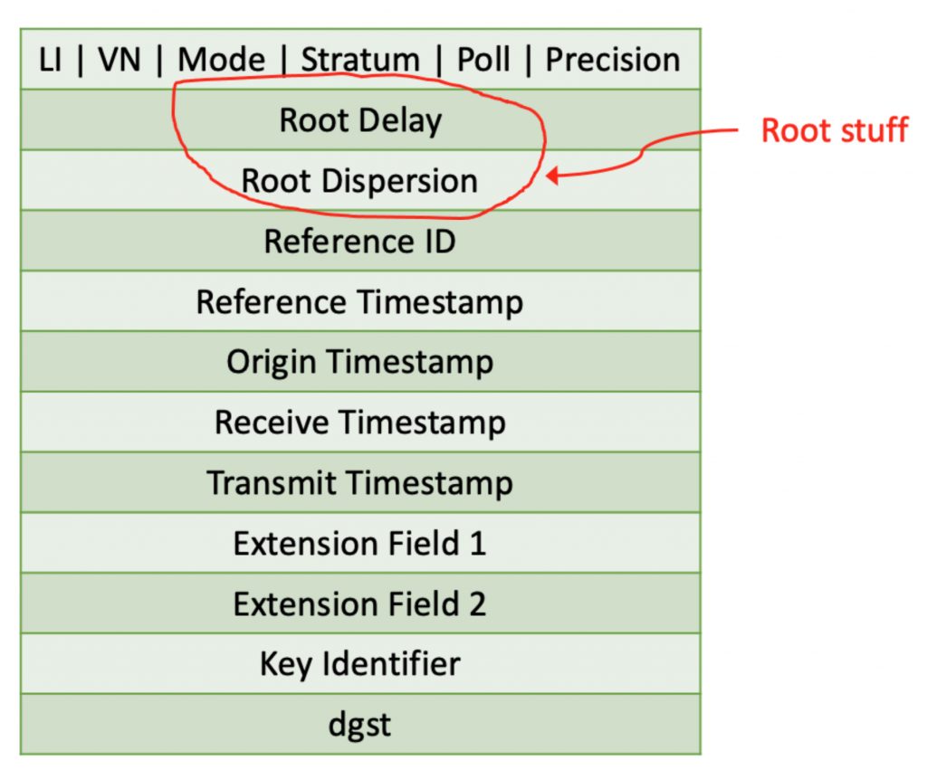
You might ask what is with all this “root” stuff? Root in this case refers to the root of the time distribution spanning tree. The root is a stratum 1 NTP server. Something that usually has a GNSS receiver to get UTC. If you are particularly fond of tree analogies, you can think of higher stratum NTP servers as branches, and clients as the leaves.
The root delay is the round-trip packet delay from a client to a stratum 1 server. This is important because it gives a crude estimate of the worst-case time transfer error between a client, or higher stratum server acting as a client, and a stratum 1 server. In fact, it is the worst-case contribution to the time transfer error due to network asymmetry, if all of the round-trip delay was in one direction and none in the other direction. Okay some of the network delay has to be in each direction, but this is an upper bound. The root delay is also used in clock steering algorithms to identify false tickers, that is servers with bad time or one’s that are sitting on the other side of a highly asymmetric network path. So, it is important.
The root dispersion tells you how much error is added due to other factors. One factor is the error introduced by a client due to the inaccuracy of its clock frequency. Using NTP the higher stratum can set its clock to the lower stratum server, but if its clock frequency is off, then an error is introduced.
Recall that an NTP time transfer involves four timestamps as shown in Figure 2.
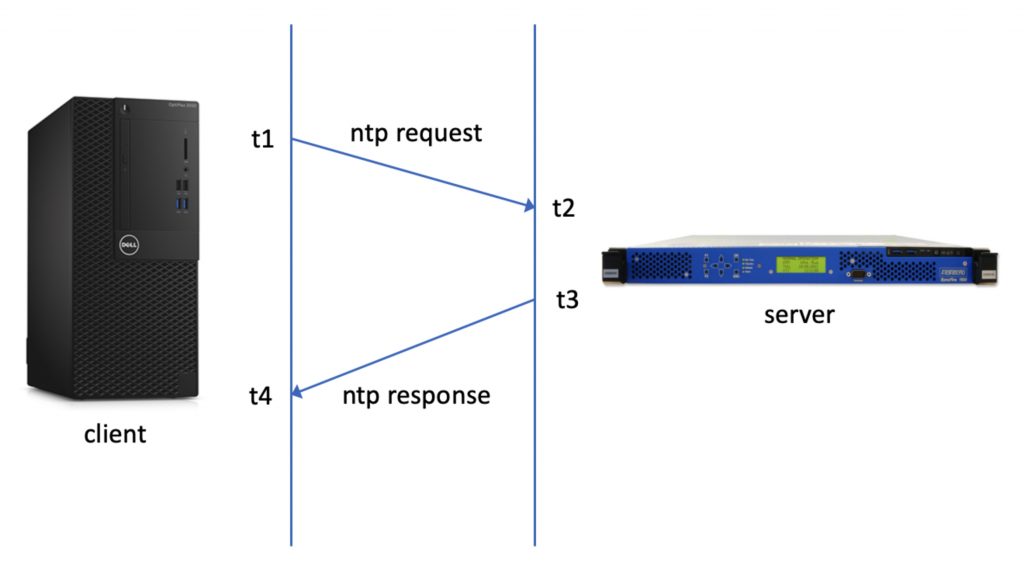
From the four timestamps the offset of the client with respect to the server is known and the round-trip delay from the client to the server and back.
Offset = [(t2 + t3) – (t4 + t1)]/2
Delay = (t4 -t1) – (t3 – t2)
Dispersion = DR * (t4 – t1) + timestamping errors
Where DR is the drift rate of client clocks time and is equal to the fractional frequency error. The timestamping errors term includes things like the errors due to the finite resolution of the clock, and delays in reading the clock when fetching a timestamp. The sum of root dispersion and half the root delay is called the root distance and is the total worse case timing error accumulated between the stratum 1 server and the client.
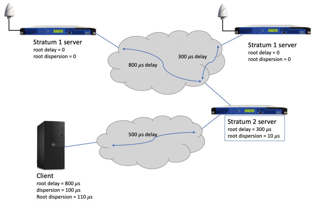
When a client gets time from a higher stratum receiver the root delay is the sum of the delays from all of the client-server pairs in the timing spanning tree. In the case when a client is getting time from multiple servers, the best root delay is used. This applies to root dispersion as well. An example is shown in Figure 3.
Okay so you are ready to amaze your friends with your mastery of NTP root delays and root dispersion.
If you have any questions about packet timing, don’t hesitate to send me an email at doug.arnold@meinberg-usa.com, or visit our website at www.meinbergglobal.com.
Why do root servers (stratum 1) have zero dispersion? While a refclock probably has no dispersion by definition, the clock following the refclock is not perfect.
Similarly for root delay: Even when the refclock is the “perfect time”, doesn’t the startum-1 server has to communicate with the refclock, introducing some non-constant delays?
You are correct that a real implementations of stratum 1 servers are not perfect. However the definitions for root delay and root dispersion in the RFCs that define versions of NTP do not include any imperfections in stratum 1 servers. In practice, it is nearly always true that the limitations of the server are negligible compared to the delay and dispersion contributions from the network.