Five Minute Facts About Packet Timing
Time to play what’s new in IEEE 1588-2019, the game where everyone wins new PTP features.
L1 Sync is short for physical layer frequency synchronization. Recall that frequency sync is also referred to as syntonization. So, what is it? First, two clocks are syntonized if the they have the same frequency. Consider two clocks emitting a series of pulses, equally spaced in time, as depicted in Figure 1.

The clocks do not transmit the pulses at the same time, but the time interval from when the clock with the upper waveform transmits a pulse when the clock with the lower waveform transmits a pulse is always the same, because the two clocks have the same frequency. They are syntonized.
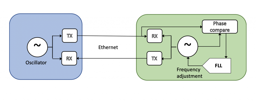
A PTP network with L1 Sync is one in which the clocks of the physical layer of the transport media are locked together. For example, look at the two Ethernet appliances in Figure 2.

An example of physical layer syntonization that is Synchronous Ethernet, known as SyncE to its close friends. Synchronous Ethernet is a standard of the International Telecommunications Union, and is commonly deployed in telecom networks.
All this begs the question, why do it? There are several reasons why you might want to syntonize your PTP network:
- Your PTP network sits between two networks that require syntonization, such as two legacy SDH networks.
- The other devices in the network can use the superior holdover the appliance acting as the frequency reference of the network
- The PTP slave servo loop will lock easier with less tracking error when the clock is already syntonized to the PTP grandmaster
- Locking the Ethernet clock together allows Ethernet based timing asymmetries to calibrated out. This is crucial to sub nanosecond performance.
Reasons 2-4 assume that the PTP ports are coherent with respect to L1 Sync. That means that the clock used for PTP is locked to the clock used for the physical layer. Reason 4 also assumes that the PTP ports are congruent with respect to L1 Sync. That means that the PTP grandmaster is also the L1 Sync frequency source. Figure 3 Shows a network that is congruent.

The source of frequency is a Primary Reference Clock (PRC) to barrow the telecommunications term. Figure 4. shows a network that is not congruent.

Incongruence is sometimes preferred so that a combined GM/PRC wont be a single point of failure. If the GM goes into a fault condition, the network can still holdover from the PRC, which generally has a very good oscillator. If the PRC goes into fault then frequency can still be derived from PTP.
The importance of congruence will be made more clear in a future post when we discuss asymmetry corrections for high accuracy PTP.
If you have any questions about packet timing, don’t hesitate to send me an email at doug.arnold@meinberg-usa.com, or visit our website at www.meinbergglobal.com.
I didn’t understand what new is L1 Sync bringing in to IEEE-1588 2019.
We already have physical-layer-frequency synchronisation required in ITU-T G.8275.1 PTP profile.
IEEE 1588-2019 does not define an L1 Sync protocol, but rather defines a general interface between PTP and any L1 Sync protocol. It also describes how L1 Sync can be used to enhance PTP accuracy.