Five Minute Facts About Packet Timing
By Doug Arnold
If are looking into network technologies for power substations, or industrial automation you may run across HSR and/or PRP. So here is the five-minute version of what these things are. First of all, both HSR and PRP are layer s network protocols, which have include the idea of sending redundant frames to increase the probability to make sure that the information gets where it needs to go quickly, even if a network element or cable fails.
Let’s start with HSR. It stands for High -availability Seamless Redundancy Protocol. The idea is to send frames, which are identical except for the path field in the HSR header, both directions around a loop. The point is that one copy of the message will get there, even if the loop is broken. See Figure 1 below.
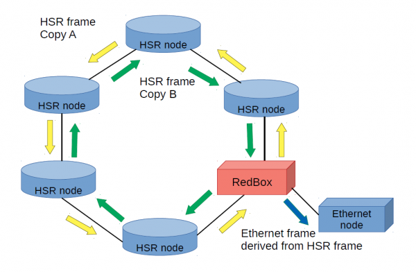
Figure 1: HSR network showing connection of Non-HSR device through a RedBox.
Network appliances which do not have the ability to communicate by HSR, can be connected to an HSR ring via a RedBox, i.e. redundancy box. The intended recipient of the redundant copies of the HSR frame passes the first copy of the message up the network stack and discards the second one. If the frames are multicast, such as with PTP, the frames circulate around the loop back to the starting point before being discarded.
Of course, an Ethernet loop is also fault tolerant using the Rapid Spanning Tree Protocol (RSTP). In that case one link on the loop is blocked to prevent circulating frames, but it can be unblocked if the loop is broken elsewhere. However, RSTP, can take 30 seconds or more to adapt to a down link, and that is simply not rapid enough for some applications. In contrast HSR is effectively instantaneous in recovering from a broken link, i.e. seamless.
HSR nodes can have more than two ports, and so can be connected in a mesh. Frames which enter one port get replicated on all others, so it is possible to create even more redundancy than dual redundancy.
PRP, the other redundant layer 2 transport protocol, standards for Parallel Redundancy Protocol. The basic idea is sending two copies of each frame down two redundant hardware paths. This is illustrated in Figure 2, which shows two PRP Grandmaster clocks sending time to two PTP slave devices.
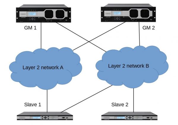
Figure 2: PTP over a PRP network. One of the PTP slaves in not redundant
Note that one of the PTP slaves is only connected to one of the networks and is therefore not redundant. That is allowed in the PRP world for devices which are not PRP capable. The PRP “header” is actually a trailer at the end of the frame which is ignored by devices which can’t use it.
HSR and PRP networks can also be joined together as shown in Figure 3.
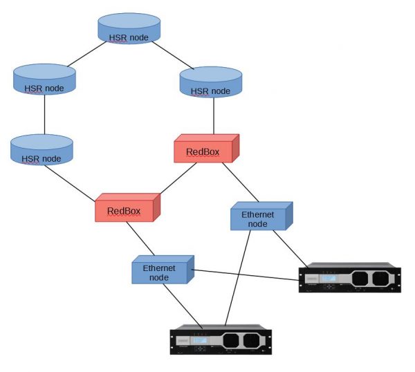
Figure 3: Combined HSR and PRP network
The IEC has included a mapping for PTP over HSR and PTP in the Power Utility Profile, IEC 61850-9-3. Such networks have been tested at ISPCS Plugfest for the last few years. Figure 4 shows participants testing PTP over HSR and PRP in Beijing at the 2016 ISPCS 2016 Plugfest. Figure 5 shows the network diagram of the HSR-PRP test network at the ISPCS 2017 Plugfest in Stockholm.
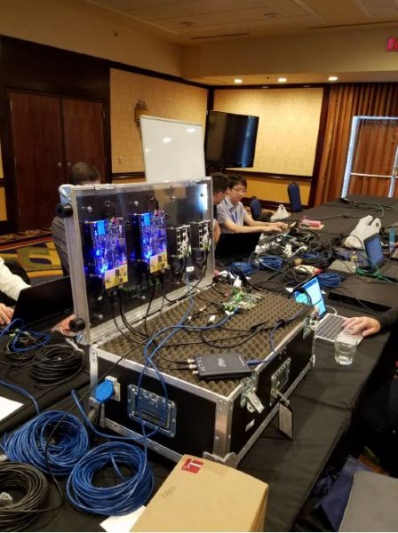
Figure 4: Participants at the 2016 ISPCS Plugfest testing HSR and PRP
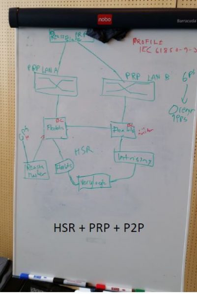
Figure 5: Network diagram from the ISPCS 2017 Plugfest HSR-PRP tests
If you have any questions about HSR and PRP or packet timing, don’t hesitate to send me an email at doug.arnold@meinberg.de or visit our website at www.meinbergglobal.com.
Great information. Since last week, I am gathering details about the Hsr and prp experience.
There are some amazing details on your blog which I didn’t know. Thanks.