By Andreja Jarc.
In a previous post I introduced tests with different IEEE 1588 / PTPv2 configurations where the PTP accuracy of the slave device was measured for each test case. The test cases performed were as follows:
- A direct link between GM and Slave as a baseline reference accuracy measurement.
- A 100 Mbit/s Boundary Clock (BC) in the PTP link between the GM and the Slave.
- A 100 Mbit/s Transparent Clock (TC) between the GM and the Slave.
- Two BCs (the same vendor and model) connected in series with and without network load.
- Two TCs (the same vendor and model) connected in series with and without network load.
- A standard Gigabit Ethernet switch, with and without network load.
PTP On-Path Test Cases
Test cases 1-3 have been addressed in Part I. In this post I will focus on tests No. 4 and 5.
Here, the performance of PTP Compliant switches, connected in series, first acting as Boundary Clocks and then as Transparent Clocks was measured and compared. Secondly, both setups underwent a stress test by injecting a high network load in the link connecting the switches, which carried the PTP messages.
Test case 4: two BCs in series
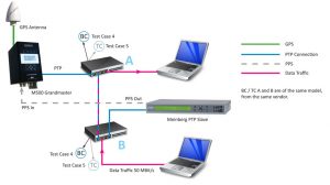
Test case 4 comprised two Boundary Clocks (BC) in series (the same vendor and model), additionally two laptops have been added to the installation in order to insert network load in the link between the Grandmaster (GM) and Slave. See the installation plan in Figure 1.
Figure 1: Setup with 2 BCs in the link between the GM and slave.
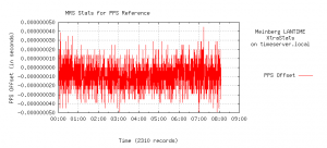
First of all, we observed the PTP performance in the network with 2 BCs in series, to see if there is a phase difference compared to the setup with only one BC. This part of the test ran for 6 hours (0-6:00 am).
In addition, the network was stressed with 50Mbit/s one way data traffic loading. This was a half of the BC switch capacity. BC was connected by a single wire attached between two laptops, which injected data load into the network. Therefore both types of packets: PTP and inserted data were sharing the same link. We checked the impact of the high data traffic in the on-path support PTP compliant network. The stress test was running for 2 hours (between 6 am – 8 am). See the measurements in Figure 2.
Figure 2: PTP performance with 2 BCs in series in the link between the GM and slave without a network load from 00:00 – 06:00 hrs. Secondly, PTP performance with a data load of 50 Mbit/s inserted in the link between the GM and the slave was measured between 06:00-08:00 hrs.
In the measurements without a data load we observed that accuracy stayed within limits ±40 ns, which is comparable with PTP accuracy of the network with only one BC clock.
Moreover, during the network stress test (between 6 am – 8 am) we observed no significant degradation in the PTP performance of the slave device as well. This is because of the specialized hardware timestamping in BC switches which mitigate the effects of timing impairments introduced by the higher data traffic between the master and slave. As a result, the accuracy stayed within designated limits of ±40 ns limits.
Test case 5: two TCs in series
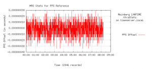
Test case 5 is similar to the test case 4, with 2 TC switches instead of BCs. Again two tests were performed, without (0-6:00 am) and with data traffic (6 am-8 am) of 50Mbit/s. The results are shown in Figure 3. In both scenarios the PTP time transfer accuracy stays within ±30 ns. This again demonstrates good PTP on path support performance.
Figure 3: PTP performance with 2 TCs in the link between the GM and slave. From 00:00 – 06:00 hrs the test was performed without data stress and from 06:00-08:00 hrs data traffic at 50 Mbit/s was inserted in the link between GM and slave. The accuracy stayed within designated limits of ±30 ns.
The test case No. 6, a setup without on-path PTP support I will introduce in the next post.
For more information about Meinberg Synchronization Solutions visit our website: www.meinbergglobal.com or contact me at: andreja.jarc(at)meinberg.de.


Hi,
In this case, the timestamping unit and data traffic is actually only crossing same path for one link.
Adding stress test with data load require to mux traffic and timestamping outside the test scope.
A more accurate setup would be
Gm-tc (mux ptp and traffic with high performance) – dut1 – dut2 – tc (mux) – slave
And ref setup
Gm-tc(mux)-tc(mux)-slave
Hello Jonas,
true, the test case could be extended with another dut1 between both tc-s.
However, in the existing setup both tcs were tested with full data loading along with ptp and they proved good on path performance, which was the scope of this test.
Hello, Andreja,
We have been your NTP server customers and we are interested in set up PTP capability.
For point to point direct fibre link (no device in between), how far can your PTP grandmaster transmit the message? Does it work for < 20km without using DWDM method?
Hello Liu Yan Ying,
apologies for my delayed response. In general, the geographical distance is for PTP transfer not critical since PTP is a timing protocol distributed over Ethernet networks. If you use a fiber link, it is important to choose the right SFP module, which supports the distances you need to bridge. Meinberg IMS Systems support PTP both either via a fiber or a copper link.
Anyway, in PTP is important that the network path is symmetric in both ways from GM->slave and slave->GM. The symmetric delays are consistently measured and compensated correspondingly. PTP aware infrastructure in the link between GM and slave is also another important issue for PTP. This means that all nodes, e.g. routers and switches should be PTP compliant in order to be able to compensate for processing and network delays and to keep the PTP accuracy.
To conclude, yes PTP can travel over longer distances. For this use the right medium (e.g. single mode fiber) and the corresponding SFP module.
Hi Andreja,
Firstly, fantastic info and some great real-world examples of what users may expect to see.
The value in investment and operation of additional switching and routing infrastructure that is PTP aware is of great interest. Accuracy vs cost and complexity for each application.
When do you estimate part III of this testing will be published? I look forward to reading the results.
Also, it would be highly valuable to understand how the accuracy of non-PTP aware switches scale… similar to your other examples where you added a 2nd TC or BC in series, it would be useful knowing this for the most basic of switches.
I look forward to hearing from you.
John
Hello John,
I wish I had a simple answer for you about non-timing aware switches. Unfortunately the effect of these switches on timing depends on too many factors. Not only is each switch different, but each network traffic pattern is different. Here are some general guidelines:
1. Simple switches impact timing less than managed switches. Routers are even worse than managed switches. The less the device looks at the packets the better.
2. Telecom profile (ITU-T G.8265.1 or G.8275.2) capable PTP equipment does better than vanilla PTP. That is because these profile are defined with non-timing aware switches in mind. They work to overcome this with PTP slave servo-loop algorithms that look for lucky packets which had little or no queuing delay. Also the telecom profiles have relatively high message rates to facilitate the lucky packet search.
3. Lightly loaded switches do better than heavily loaded switches since there is a better chance for lucky packets. Also traffic with smaller packets is better. When a Sync message is stuck waiting for packet to finish exiting a switch through the port the Sync message needs to exit, it matters how long that interfering packet is. Streaming video is the worst, since it is a lot of maximum size packets.
4. The more stable the oscillator of the PTP slave, the more filtering it can do on the incoming timing stream. So specialized timing hardware solutions with good oscillators do better than software running on a Linux server.
I know that some high frequency traders get sub-microsecond time transfer through non-timing switches. However, they use the fastest switches which money can buy, in a shallow network (2-4 hops) with light traffic (e.g. 30% loading) and small packet sizes.
If you tell me about your network, I can make an educated guess as to the performance. But ultimately you might want to make some measurements on your network, using ptp clocks which both have GPS, or are synchronized to each other with a dedicated timing cable.
Doug