By Andreja Jarc.
This time I prepared some experiments with different IEEE 1588 / PTPv2 configurations where the accuracy of the end device was measured for each test case. In all Test cases a Meinberg M500 IMS (modular platform in a railmount formfactor) was used as Grandmaster (GM) and a Meinberg SyncBox as a PTP slave.
Subsequently different type of switches were added in the link between GM and slave. The switches were either PTP compliant, or a standard Gigabit Ethernet switch which is unaware of PTP. The PTP compliant switches were acting as a Boundary or Transparent clock, all from the same vendor, but not Meinberg. After all nodes had been properly synchronized, the accuracy of the PPS output of the slave was measured against the GPS sync PPS on the master system to determine PTP performance in the small network. The results are shown below in order which the test were performed. In this blog post I will present results from the first three test cases. The rest will be presented in a subsequent post.
Test cases scenarios:
1. A direct link between GM and Slave as a baseline reference accuracy measurement.
2. A 100 Mbit/s Boundary Clock (BC) in the PTP link between the GM and the Slave.
3. A 100 Mbit/s Transparent Clock (TC) between the GM and the Slave.
4. Two BCs (the same vendor and model) in series with and without network loading.
5. Two TCs in series with and without network loading.
Test case 1:
A direct link between a GM and a slave. The PTP configuration of both PTP nodes was as follows:
• Default E2E Profile (multicast)
• Network Protocol: UDP/IPv4
• Announce Message Interval: 2 seconds, Sync Message Interval: 1 seconds, Delay Request Interval: 8 seconds
• PTP card used for GM was a Meinberg TSUv3 (Gbit)
• PTP card used in the slave was Meinberg 10/100Mbit TSU
1PPS generated by the slave PTP card was serving as an extra PPS Input signal for the GM. This kind of setup enables measuring PTP accuracy of a slave compared with a GPS reference of the master. The measurements can be found in the Web GUI, from there follow to the Statistics dialog (XtraStats) where logged data for the incoming PPS signal is stored. The data can be conveniently depicted in graphical form as well. This is one possible approach how to measure PTP accuracy of a slave and thus also PTP performance of the network.
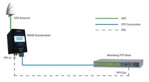
Figure 1: The setup of Test Case 1, a direct link between the GM and the slave. The experiment ran for 7 hours, PPS Offset (phase difference) was measured against the GPS steered internal clock of the GM.
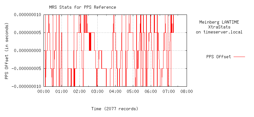
Figure 2: PTP accuracy of the slave compared to the GPS reference in the master, with a direct connection between master and slave. PTP performance stays within ±10 ns accuracy range. Note the very high 5 ns measurement resolution which was sampled with Meinberg’s latest GPS180 receiver installed in the GM.
Test case 2:
A Boundary Clock (BC) from another vendor was inserted between the GM and the slave. The configuration on the BC was set the same way to match master / slave PTP configuration (see details in Test case 1).
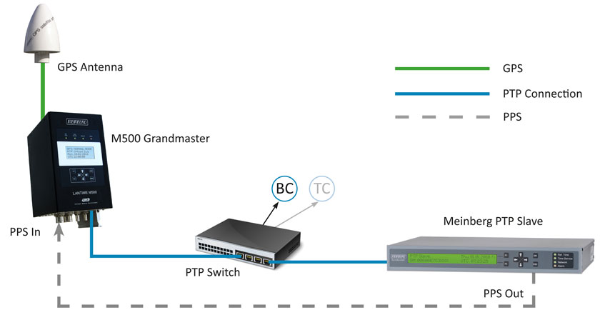
Figure 3: Setup of the Test Case 2 and Test Case 3. Each testing scenario ran for just over 7 hours.
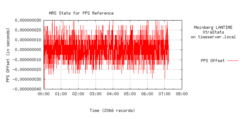
Figure 4: PTP performance of Test Case 2 (a BC in the link between the GM and the slave). The jitter increases by inserting a BC, but still it stays well maintained within a ±30 ns bounds.
Test case 3:
A TC between master and a slave. The connection scheme resembles Test case 2, except the BC was replaced by a TC.
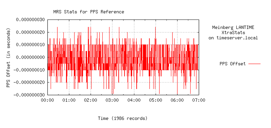
Figure 5: PTP performance of Test Case 3 (TC in the link between the GM and the slave). Less jitter can be observerd in comparison with the setup including a BC. There are occasional jitter spikes, but these stayed within ±25 ns.
The main difference between a BC and TC is that a Boundary clock comprises its own local clock which is synchronized first with PTP coming from a master and then it sends its own generated PTP packets via a master port forward into a network. A Transparent Clock on the other hand forwards PTP messages directly from a master into a network with a correction field updated for the residence time spent in the switch. Due perhaps to this less complex mode of operation the TC contributes less jitter than a BC, as it is obvious from PTP performance in Figure 5.
Moreover, PTP packets generated by a BC get timestamps from an internal clock which is by quality and stability lower graded than from the GM which can be another source of jitter. However, even a BC in our tests stays within a ±30 ns bounds.
This was a 5-minute post for today.
For more information about Meinberg Synchronization Solutions visit our website: www.meinbergglobal.com
thanks for great post.
Please help me with some basic question.
1) how the 1PPS output pin works
2) what would happen on master and slave devices 1pps pin when sync is egress/ingress.
Hello Nousilal,
1) PPS output is a BNC interface, at TTL level
2) A master system can use PPS as input and/or output, whereas slave only as output.
The TSU card contains a local clock used for PTP, and the 1PPS output indicates the start of each second for this local TSU clock When the TSU is acting as a master, the 1PPS of the TSU will be almost the same as the clock card, since the TSU local clock will be phase locked to the system clock through the backplane.
When the TSU is a PTP slave, it will steer the TSU clock to the PTP master. If the System clock is using PTP as its current reference it will steer itself to the TSU clock, so the 1PPS outputs will again be almost the same. However, if PTP is not selected as the current active reference, but only a backup, then the 1PPS signals of the system clock and the TSU clock might be different.
what could be max and min phase difference between master and slave end points if there is an one TC between them.
Min phase difference of a TC is ideally 0 and max, depending on deployment, in the power profile for example is 50 ns.
Interesting post but I am most interested in the test case 6. When do you think the part II will be published ?
Regards.
Thank you for your feedback. I intend to publish the second part soon, I will keep you updated.
Also look forward to the second part)
Hi Andreja, how are you ?
we would like to do the test like your Test case #1 but with the following changes :
Instead using M500 as GM we would like to use M500 as a slave PTP and would like to measure the PTP slave accuracy compared to GPS input, in our case we would like to use only one unit of M500 as PTP Slave and not 2 units GM & slave as in your test case.
Thanks for you help
Avi hello. I am good, thanks! I checked if you could perform the test with only one M500, but this is not possible. For the test you need 2 PTP cards, one running as a GM and the other as a slave. And for comparison of the PTP accuracy against the GPS you would need an extra MRI card. This means altogether 3 slots, but M500 has only 2 free spaces.
Let me know if you need more help.
Hi, thank you for this post the best part is 1PPS generated by the slave PTP card was serving as an extra PPS Input signal for the GM. This kind of setup enables measuring PTP accuracy of a slave compared with a GPS reference of the master. very useful information
Hello ma’am
Good morning
Can u brief about how 1PPS signal is generated from PTP network?
Hello Jayashree,
apologies for my delayed response. Thank you for your question. Well, a PTP slave, in our case Meinberg SyncBox is also a clock, which steers its servo loop according to the master clock. It means, that a slave has its own oscillator. And the oscillator, when sync to the master clock, it generates PPS as an output signal.
Hi Andreja
Thanks a lot for sharing this . I have a question though. What tool and set up you have used to calculate the PPS Offset against PTP at GM Clock by receiving PPS via the Slave clock.
In this case the PTP GM has the capability to measure a 1PPS input compared to its own system time. In cases where that is not available then one can use a high frequency oscilloscope of a frequency counter to compare 1PPS signals between the GM and PTP slave.
Hello
I’d like to setup these test.s
as grandmaster , I have a M1000 ,with module MRI
as client, I have a PCIe board from Oregano
I have connected the PPS output of Oregano board on PPS input of MRI module on M1000
But I’m not able to hav access to these kind of graph on web interface of M1000
Thank you for your help
Regards
Laurent
I recommend the use of Meinberg’s SyncMon system for this. See: https://www.meinbergglobal.com/english/products/ims-measurement-modules.htm.