Five Minute Facts About Packet Timing
By Doug Arnold.
Which delay measurement mechanism is best for deploying IEEE 1588? Since I’m an engineer, the answer is, of course, it depends. The short answer is that the peer-to-peer delay measurement mechanism is best in an engineered network, where all switches (and routers if there are any) can be guaranteed to be 1588 capable, i.e. they are either transparent clocks or boundary clocks. If there are going to be any non-1588 aware switches, or if there is any doubt about this, then you want the end-to-end delay measurement mechanism.
Why this is the case should become apparent as we review how these two mechanisms work. The end-to-end delay mechanism was described in my previous posting, Why is IEEE 1588 So Accurate. In peer-to-peer networks the master still sends Sync and Follow_Up messages to the slave clock just as with the end-to-end delay measurement mechanism. With peer-to-peer the slave calculates its clock offset with respect to the master as follows:
slave time = master time + network delay.
No need to combine four timestamps like we did with end-to-end networks. But wait, how did the slave know the network delay? That is the magic of the peer-to-peer delay measurement mechanism. Instead of sending delay measurement messages from the slave to the master, as with the end-to-end approach, each device on the network exchanges peer-delay measurement messages. That way each device can keep track of the delays between itself and its immediately connected neighbors. The diagram below shows how this works.
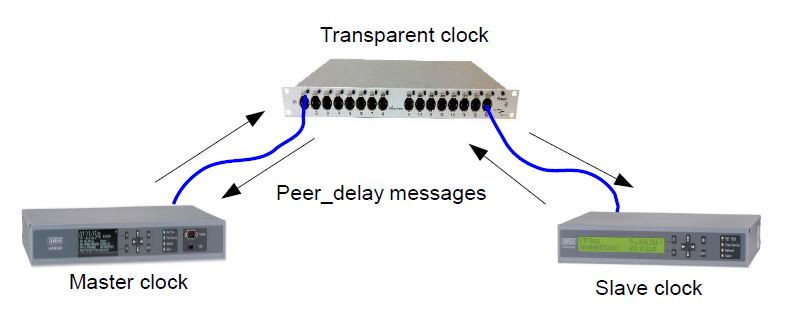
Each device periodically initiates an exchange of peer-delay messages on every connected port. Then each device removes the peer-delay from Sync messages when it enters the device, by updating the correction field in either the Sync or Follow_Up message. If its a switch, it doesn’t include the peer-delay in the out going cable, even though it also knows that. The next device in the chain will do that correction, and we don’t want to double count.
The sequence of peer-delay messages looks like this:
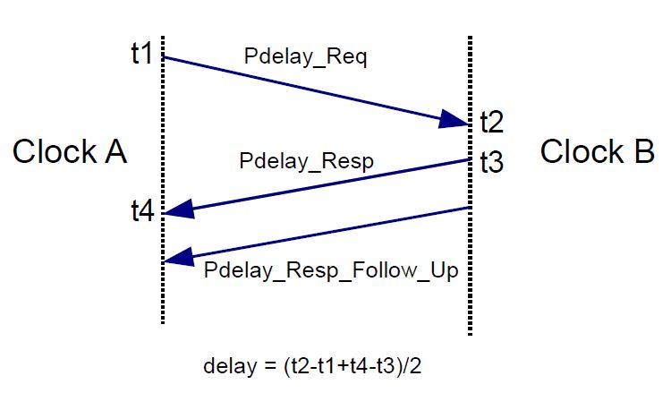
Clock A wants to know the delay to Clock B. So it sends a Pdelay_Req messages, short for peer-delay request. Clock A also saves the time it sent that message, t1. Clock B saves the time, on its clock, when this message arrives, t2. Then Clock B sends a PDelay_Resp message, short for peer-delay response, and a Pdelay_Resp_Follow_Up. The follow up message contains the departure time for the Pdelay_Resp, t3. Clock A also saves the arrival time of the Pdelay_Resp, t4, so it has all of four timestamps and can calculate the delay between the clocks. If you saw my earlier post, where I described end-to-end delay measurements, this all looks pretty familiar, and it turns out we have to deal with the whole four timestamp business anyway. Clock B will also initiate the same series of messages in the reverse direction so that both clocks know the peer-delay.
Here, as with the end-to-end mechanism, the assumption is made that the time it takes for the peer-delay messages to get from one clock to the other is the same in each direction. In the peer-to-peer case we only making that assumption over a cable, not the whole network, and there are no queues. So unless the cable is very long, that is a good assumption.
What about the queues in the switches? At the beginning of this post I said that peer-to-peer only works well when every switch is either a transparent clock or a boundary clock. That way the switch will take care of its own queuing delays. Another reason that we don’t use peer-delay with ordinary switches is that the switches don’t know what to do with peer-delay messages, and will not respond to them.
Although the end-to-end mechanism is more versatile, because it can handle ordinary switches and routers, the peer-to-peer mechanism has several advantages in networks where it does work:
- All links are periodically measured, so delay between the master and slave are already known when the network path changes. Note that peer-delay messages are exchanged even on ports blocked to prevent loops, such as by the Rapid Spanning Tree Protocol.
- There is no chance of Sync and Delay_Request messages taking different paths, since there are no Delay_Request messages.
- There is no need to worry about the master clocks ability to respond to Delay_Request messages when there are a lot of slaves, it only has to send the Sync and Follow_Up.
If you have any questions about PTP or hardware timestamping, don’t hesitate to send me an email at doug.arnold@meinberg-usa.com, or visit our website at www.meinbergglobal.com.
I have a question. In the peer-to-peer mode, I don’t know the way how the clock A get the timestamp t2( save in clock B) in order to calculate the network path delay. Thanks.
Here is the sequence:
Clock A (t1) — Pdelay request —> (t2) Clock B
Clock A (t4) <— Pdelay response — (t3) Clock B
Clock A <— Pdelay response follow up — Clock B (only if Clock B is two-step)
If clock B is a two-step clock then the t4 timestamp is sent with the Pdelay follow up message. If Clock B is a one-step clock then t4 is placed in the correction field of the Pdelay response. Either way the Pdelay response includes a field for the t2 timestamp.
The PDelay_Response contains the arrival timestamp of PDelay_Request message.
Hi Douglas Arnold,
Can you explain more on neighbourhood rate ratio in case of Peer to Peer TC.
As per my understanding in case of Peer to Peer Transparent Clock device, it is not necessary to synchronize instead syntonization(frequency correction) is good enough. In such scenario I am getting the meanlink delay to be of negative value. This is happening when the Pdealy responder time is ahead of the Pdealy Requester time.
Such things can happen (meanlink delay to be of negative value)?
Regards,
Srinivasa
Hello Srinivasa,
Neighbor rate ratio is used to adjust for the differences in frequencies between the clocks in adjacent devices on the network. The idea is that a slave clock is not steered to the master fewquency but rather the difference in frequencies is calculated and time stamps from the local clock are corrected for this difference. Usually that means that the phase offsets between the clocks is handled in the same way. The only profile, I know of that makes use of this is IEEE 802.1AS, a profile which does not include transparent clocks.
The PDelay responder time being ahead of the PDelay requester should not make the meanLinkDelay negative, because the Pdelay calculations takes into account the offset between the clocks.
Maybe a large enough difference between clock rates could result in an adjustment which makes the meanPathDelay negative, but that is not expected in a well engineered timing system. It is more likely that something is wrong.
Doug Arnolf
Hi Doug Arnolf,
Thanks for the reply.
In case the clock frequency of Transparent clock w.r.t. Master Clock is more than 200ppm such things can happen? (negative link delay)
Does the protocol has any limitation in non-source synchronous interface (like RGMII)? We are facing issue in this port not on the other source synchronous ports…
Regards,
Srinivasa
Hello Srinivasa,
No. IEEE 1588 does not place any limits on the frequency alignment of physical layer circuit oscillators and the PTP clock. The general philosophy of 1588 is to leave performance specs to profiles. I don’t know of any profiles which address this specific issue. Usually they have a blacket spec for the error of the clock, like 50 ns, due to all error sources.
Some 1588 implementations will lock the PHY oscillator to the PTP clock, to reduce that error. Other implementations are capable of Synchronous Ethernet so PHYs of all the clocks in the network are syntonized.
Doug
If the frequencies of the two clocks on either end of a link are different enough, then it is possible that the calculated peer delay for this link will be negative. However, once the accumulated rate ratio and total link delay are taken into account at the end of the timing chain, errors will cancel, and end slave will have the correct adjustment to its clock.
Thank you for this great article. Much easier to read than the standard itself.
I have one Question. Why
slave time = master time – network delay
and not
slave time = master time + network delay?
Thank you and kind regards!
Matthias
Hello Matthias,
Thanks. You are right. I’ll fix the post.
Doug
Hello Doug,
Very informative and useful post! Just like all the others.
I had a question on the following statement:
“The short answer is that the peer-to-peer delay measurement mechanism is best in an engineered network, where all switches (and routers if there are any) can be guaranteed to be 1588 capable, i.e. they are either transparent clocks or boundary clocks.”
Should this be:
“… can be guaranteed to support P2P TC….” ?
I mean to ask, if you have a boundary clock (that does not support P2P TC) as a peer of a P2P TC, how will the delay measurement work? Is it any better than having a non-PTP capable peer?
Please correct me if I am missing something.
Thank you!
Vaibhav
Also, is the resilience to network path changes similar for E2E TC and P2P TC or is P2P TC better in this respect? If P2P TC is better, could you please explain how?
I am referring to the following point:
All links are periodically measured, so delay between the master and slave are already known when the network path changes. Note that peer-delay messages are exchanged even on ports blocked to prevent loops, such as by the Rapid Spanning Tree Protocol.
If the Delay Request interval in the End-to-End mechanism is longer than the Sync interval, then there could be some Sync messages which would be associated with obsolete path delay information right after a network configuration change. This would not happen with Peer-to-peer since all paths are measured in the background all of the time. This was a concern when the 2008 version of 1588 was released since it was common practice at that time to configure Delay Requests to be less often than Sync messages. Currently it much more common to configure Sync and Delay Requests with the same message interval.
There are also some rare cases where a network rearrangement or traffic management scheme can cause the Sync and Delay Requests to take different paths. Again this is never an issue for the peer-to-peer mechanism.
Makes sense, thanks a lot!
Thank you, you are correct. It is not enough to support PTP, the switches must specifically support the peer-to-peer mechanism.
Hi,
Really nice article. I have a question related to IEEE 802.1AS document topic “Media Dependent Layer Specification for full duplex Point to Point Links”
I am implementing Ethernet Time Synchronization Module for Media Dependent Layer.
Question: When System gets initialize Is Master will send Sync Message in start or Both ends will calculate Propagation delay?
I am using Double clock means. In start master will send Sync Message & after a delay it will send a Follow Up Message.
Please explain, m confused here . thanks
Hello Zubair,
The 802.1AS profile of IEEE 1588 exclusively uses the peer to peer propagation delay measurement method. In this method each port sends peer delay measurements to the port it is connected to, gets a response and determines the link delay. So over any cable in the system peer delay messages and responses go in both directions, initiated independently by each port on the link. This way every port knows the propagation delay of the link it is attached to regardless of which direction the sync message goes.
For two step clocks the master port sends a follow up message after the sync which contains the time which the corresponding sync message left the port. The purpose of the follow up message is to provide a more accurate departure time than the sync message contains. This two step property is needed by clocks which do not have the ability to place an accurate timestamp in a message as it is leaving the port. The follow up messages should leave as soon after the sync message as it is ready, there is no reason to delay sending the follow up message once it is constructed.
Hi Doug,
Great article. I have a couple of quick question on resilience.
I’m looking to deploy two identical, GPS locked GMs on the same network. I’ll adjust the Priority 2 value to be different between the two to allow BMCA to select one over the other. On a P2P deployment, where there are two GMs, do both GM’s announce themselves to the same PTP multicast group address continually? I.e. Is the failover between GMs down to the receiving endpoint detecting Announce messages from both GMs, running the BMCA and selecting the best GM (which will by default be the one with the higher Priority 2). Alternatively, do the GMs monitor one another and select the best GM amongst themselves, such that only one set of Announce messages is present on the network?
Also, I have symmetrical network path resilience between my two GMs and receiving endpoints. My GMs are connected to two core network switches. Access switches are connected to both cores for resilience. Receiving endpoints to the access switches. I’m looking to run IGP and PIM on the network and ECMP on the access switches. This is because I believe that when a receiving endpoint performs an IGMP join to the PTP multicast group, where equal cost routes exist between a receiving endpoint and GM multicast group, PIM will default to the core with the lower IP address. ECMP should spread the load between cores, which is preferable. Does this sound sensible to you?
Many thanks in advance,
Grant.
Hello Grant,
You have a bunch of good questions.
Re Priority_2 fields:
Adjusting the priority_2 fields allows you to know which nominally identical GM will be primary and which will be a passive backup. However, if you don’t set the priority_2 fields different, then the GM with the lowest clock_id will be primary. So, either way there will be a primary GM and a backup, but adjusting priority_2 means you get to pick and don’t have to check clock_ids to know which is primary. Note, the clock_id is usually the Ethernet MAC address.
Re BMCA:
In multicast PTP, all master capable ports participate in the BMCA. If a master capable port sees an Announce message from a better clock it goes passive and does not send Sync and Announce messages. Except for transient situations when there is a change in GM, the slaves only see Sync and Announce from the best master.
Re Load balancing vs. fixed network paths
In a P2P implementation of PTP, it really doesn’t matter. Peer delay messages will be used to determine, and adjust for, the delays of all links separately. Use whichever routing scheme works best for your applications. In an E2E network load balancing routing protocols are undesirable since the Sync and Delay_Request messages may go on different routes, creating a propagation delay asymmetry. Remember that E2E PTP assumes that the forward and reverse delays are equal, and any asymmetry results in an error in the calculated slave clock offset.
hai,
great article..very precise information…..
iam recently get a chance to work on ptp. so, i request you to provide more precise documents on ptp to my mail…if possible or suggest me any links..
thanks..
Hello Chandra,
contact me at andreja.jarc[at]meinberg.de to help you further with PTP.
Kind regards,
Andreja Jarc
thanx..
but how to start basics of ptp and why ptp come into picture and advances of ptp. help me on these.
thank you.
main difference between end to end and peer to peer transparent clocks.
thanks
Please explain difference between end-to-end and peer-to-peer delay measurement ?
Is it end to end delay measurement meas delay between grand master and slave ?
Please explain this two with typologies .
Why (t2-t1+t4-t3)/2 instead of ONLY t2-t1 which gives the delay between master and slave and slave can use this to adjust its clock. Why does slave need to know the delay from slave to master as well?
If both the delay between the clocks and the offset between the clocks are unknown, then we have to solve for both. If you do the math you will find that you need to use all four times stamps to determine either the delay or the offset.
In below description you mentioned “remove”. But it suppose to be “addition”. Please correct me if i
my understanding is wrong.
“Then each device removes the peer-delay from Sync messages when it enters the device, by updating the correction field in either the Sync or Follow_Up message. “
Dear Arnold,
I have read the your post about “Modular TC” and the 2017 version(draft) of the standard, here is some questions and ideas I would like to share with you.
1.It seems like for TC, now only the “Egress Port” has the attribute of “stepness”. So can we say that, the standard is trying to simplify the Ingress, and push most of the work(e.g. stepness modification) to the Egress?
2.As we are adding more features on TC, does it means TC is more recommended in the future? I mean in real application, is there any reason that will force us to use TC instead of BC?
3.Following the previous question, in my point of view, the P2P-TC and P2P-BC are almost the same, the only different is how they process Sync/Follow_Up and not involved in BMC. It feels like the P2P-TC is a little bit redundant. Is any specific scenario that we have to use P2P-TC?
It would be really helpful if you could answer these questions and point out my mistakes.
Best,
Lee
1. Actually ingress ports could have stepness as well. The complications around stepness was put in to 1588 to deal with modular TCs, such as one which has a back plane and separate cards for each port. In such a device it might be possible for the ingress port and egress port to be of different stepness.
2. An advantage of BCs is that they breaks up a large PTP network such that PTP messages do not have to go between the Grandmaster and every slave. Instead a slave port can communicate with the nearest BC. The advantages of TCs is that it easier to see what is going on. All of the multicast PTP message are visible anywhere in the network, except peer delay messages if you have them.
3. The first edition of the power profile, IEEE C37.238 specified that all switches shall be TCs. Since then, the latest edition of the power profile and the similar utility profile (IEC 61850-9-3) allow BCs and/or TCs. However TCs are more common than BCs in the power industry. One more advantage of TCs is that they are stable with respect to growth of timing errors in a long cascade of switches. If there are many BCs in a cascade, and the gain peaking is set too high on the servo loop, then timing errors can grow exponentially with the number of hops. Note that the IEEE 802.1AS profile includes cascaded P2P BCs, but the BCs do not have a servo loop, so the problem is avoided.
Dear Arnold,
I need to know answers for the following few questions.
1. In peer delay mechanism, do we need to send sync message?
2.Can you explain in detail how timestamp t2 is known by the requester node.
3.If master-slave path is same, should I want to calculate delayAymmetry?
4.Where we will pass the timestamps? In correctionField or orgineTimestamp?
5.If master-slave path is same, should I want to calculate meanPathDelay for both master as well as slave?
1. Peer delay messages only gather the information needed to determine the propagation delay of a link between PTP nodes. A port in the slave state still needs sync messages to determine the time.
2. In the peer delay mechanism, the t2 timestamp is sent from the responder in the Pdelay_Resp message (1 step) or Pdelay_Resp_Follow_Up message (2-step).
3. Even when the master-slave and slave-master path is the same, there is still asymmetry due to the asymmetry of Ethernet PHYs, and cables. In the case of cables the asymmetry is due to the different number of twists in copper wire twisted pairs, or in different colors in a fiber. These sum total of these effects are typically less than 100 ns in a local area network. They can be larger for networks with many hops or long fiber runs. So it depends on the size of the network and the requirements for time transfer precision. Note that asymmetry must be measured by means outside of PTP. IEEE 1588-2019, which will be available soon has information on how to perform the asymmetry measurements.
4. Usually timestamps are the PTP timestamp fields of PTP event messages. However, the timestamp fields only have a resolution of 1 ns. If the timestamp clock has sub-ns resolution than the sub-ns part will have to be added to the correction field.
5. You do not necessarily need to calculate the meanPathDelay for the slave, but it is generally done, since the slave has all of the information. The master does not calculate the meanPathDelay since it does not have all of the information.
Hi Douglas Arnold, I’d like to know how to calculate the time taken to select GM. Assuming that there is a TSN network composed of 10 clock nodes, does it take at least 10 announce intervals to determine GM? Because in the worst case (for example, when the best clock node in a linear network is at both ends), it takes 10 intervals for announce information to pass from the best node to the end node. Is that the case?
You are correct that it can take this long as a worst case. However, it is often faster. For example if a BC receivers a Announce message in the middle of its Announce transmit period, it can transfer the information before the next Announce messages are transmitted.
Hello, I have a question to confirm. in TSN network the time cost to determine GM is strong related to the total number of nodes and the announcement period. the maximum time is the number of network nodes multiplied by the announcement period. Considering the most extreme case, assuming that at the head end of the best clock node in a linear network, the time required to transmit the announcement information to the end node. Is this conclusion correct?
Your conclusion is correct for the worst case analysis. In practice the BMCA might be faster. For example a BC can receive an announce message in the middle of its own announce transmitting interval and put information from the received announce in the next transmitted announce message.
Hello,
I have one confusion.
In TSN, when a GM fails, the closest gm-capable instance sends announce message declaring itself as new GM and announce messages are forwarded until a new GM is found.
My question is when the new sync messages will be sent by the new GM?
For example, in a linear network of 4 nodes (1-2-3-4), 1 is the GM, and 4 is the potential GM, then when 1 fails, and 2 sends announce message considering itself GM, is it start also sending sync message or it waits for a period to be sure it is GM or not.
And if starts sending sync messages then, afterward when node 4 becomes GM, what happens to this sync message sent by node 2.
And how long node-4 will wait before sending a sync message?
Before transitioning into the grandmaster role, a master-capable device will wait for the announce time-out interval to elapse since the receipt of an announce message by the previous grandmaster. A typical value for the announce time out interval is three announce intervals. However in larger networks, it is possible for a master capable device to not receive an announce message from the new grandmaster before the announce receipt time out elapses, due to delays in the network. So a grandmaster change can result in some transient effects in the network.
Doug
Hi Douglas Arnold,
I am new to this domain
I am currently working in 802.1AS-2011 automotive profile .
I have some doubts i.e
1.if there is two clocks then by using sync messages they try to synchronize and then calculate path delay by pdelay messages to reduce the error in synchronize upto this i am clear. But i am not able to understand
what is need of frequency correction (syntonization) ,Mean delay link.?
2.Assume there AVB Talker –AVB switch–AVB listener,then if listner send Pdelay request messages ,then corresponding pdelay respesonse messages are received from switch.
my question is
whether these response messages are newly generated by switch or it is forwarding from talker?.
Syntonization (frequency synchronization) is not required in 802.1AS because of the neighbor rate ratio measurements and cumulative rate ratio updated by each Boundary Clock. Transparent clocks operating in profiles that do not use the rate ratio technique should syntonize their timestamping clock to reduce the error in determining the residence time of PTP event messages due to frequency inaccuracy.
Doug,
In one of your responses, you stated “IEEE 802.1AS, a profile which does not include transparent clocks.” In 802.1AS, the standard mentions about syntonized peer-to-peer transparent clocks.
Are the 802.1AS Bridges or Relay Instances implemented as Boundary Clock or Transparent Clock or both ? I notice there is switch vendor states their P2P TC support 802.1AS.
IEEE 802.1AS bridges are really a hybrid of BCs and TCs. They act like a BC with respect to the PTP protocol, updating steps removed and running the BMCA. However, from a time synchronization point of view they are TCs, They do not have to synchronize themselves to the Grandmaster, but add a correction and pass it down the line.
Hi Douglas
I am having a question with PTP with Power Utility profile. We currently have a GPS clock and the PTP messages of clock are Vlang Tagged.
The GPS Clock (Grandmaster Clock) and Slave clock are connected to each other via switch who act as a transparent clock.At Transparent clock we have tried both enabling and disabling the VLAN.and we have mirrored port from slave clock (Ingress and Egress) at switches (Who act as a transparent clock)
While capturing the packets from wireshark we have observed that we can not see the Peer_Delay _Response (Response of Peer_Delay _Request from Slave Clock) from Grandmaster.
Also we have not see the packet from Peer_Delay _Request from Grand Master Clock as well.
Is this a correct behaviour while using a PTP with VLAN?
Hi Douglas,
My ptp ethernet switch at p2p mode calculates ethernet switch delay – link delay and sets correction field. Do I still need to send delay req / resp messages to calculate delay between nodes?
If you are using peer delay, then you do not need delay request/response messages. The peer delay messages will account for the network propagation delay so that the time stamp in the Sync or Follow Up message can be adjusted.
Hi Douglas
i really enjoyed this post.Understanding the dynamics of end-to-end and peer-to-peer systems is vital for anyone navigating the world of communication and data transfer.
Glad you found it useful. E2E vs P2P is a common question I get, although usually it gets settled at the PTP Profile definition level, rather than the end user configuration level. You pick a profile, and assume that experts from your industry made a sensible choice in a standards committee.
The spec says in section 11.4.1 on page 199, “For Boundary Clocks and Ordinary Clocks, the peer-to-peer delay mechanism shall be independent of whether the PTP Port is in the MASTER or the SLAVE state.” What is the benefit having slaves respond to peer-to-peer delay requests? If slaves don’t respond to peer-to-peer delay requests, then the mechanism can work even if non-PTP bridges are involved such as in Figure 43. We are making a slave-only device. We are trying to understand why it needs to respond to the Pdelay_Req messages.
Excellent question. The reason slaves are required to respond to Peer Delay messages is such that in network of BCs all paths are pre-measured so that Synchronization can be achieved rapidly upon a rearrangement, i.e. change to a different GM in a different position in the network. The IEEE 1588 working group members who supported the inclusion of Peer Delay in PTP assumed that all switches would be PTP capable and they were very concerned about settling time after a rearrangement.
Furthermore, even if slaves did not respond to a Peer Delay Request Peer Delay capable TCs would respond. So a Peer Delay Request sent to a an ordinary Ethernet switch could be forwarded to multiple TCs, all of which respond. It might be possible to extend the Peer Delay mechanism to sort this out, but there was no interest in taking this on in the working group.